
Iowa Redesign
Retrofit of the U.S.S. Iowa. This will not come to anything, but it's fun for me to stretch my brain.
- 1. Summary of Project
- 2. Main Goals
- 2. 1. Additional Goals
- 2. 2. Mandatory Capabilities
- 3. 1. USMC Fire Support
- 5. Superstructure, Hull, and Signature Reduction Systems
- 5. 1. Hull
- 5. 2. Superstructure Modifications
- 5. 2. 1. Bridge Modifications
- 5. 2. 2. Multimission Bay
- 5. 2. 3. Modular Weapon Mounts
- 5. 4. Turrets
- 5. 5. Propulsion/Propellers
- 5. 6. Ship Silencing Information
- 6. 1. Main Power
- 6. 2. Supplementary Power
- 6. 3. Power Distribution
- 7. 1. Cannon
- 7. 1. 1. 16 inch Ammunition Propellant System
- 7. 1. 1. 1. Theoretical Propellants
- 7. 1. 2. 1. 5 inch guns
- 7. 1. 2. 2. Advanced Gun System (AGS)
- 7. 1. 2. 3. Other Secondary Battery Weapons
- 7. 2. 1. Existing 16" Ammunition
- 7. 2. 2. Improved conventional ballistic rounds
- 7. 2. 3. ''Cutlass'': GPS/INS guided rounds
- 7. 2. 4. Antiaircraft and Antimissile (AHEAD/ABW)
- 7. 2. 5. Multiple Warhead Shell
- 7. 2. 6. SADARM Round
- 7. 2. 7. Thermobaric Round
- 7. 2. 8. Sub-Caliber SABOT round
- 7. 2. 9. RAMJET/SCRAMJET Rounds
- 7. 2. 10. Secondary Battery Ammunition Types
- 7. 1. 1. 16 inch Ammunition Propellant System
- 7. 4. Missile Systems
- 7. 5. Torpedo Systems
- 8. 1. Passive Defenses (Armor)
- 8. 2. Electronic Counter Measures
- 8. 3. Decoy Launch Systems
- 8. 4. Decoys
- 8. 5. Point Defense Systems
- 8. 5. 1. Close in Weapon Systems
- 8. 5. 1. 1. Archerfish
- 8. 5. 1. Close in Weapon Systems
- 9. 1. Sensor Suite
- 9. 2. EW Suite
- 9. 3. Communications Equipment
- 9. 4. Sonar Systems
- 9. 5. Radar Systems
- 9. 6. Optical Sights
- 10. 1. Network
- 10. 2. Computer Hardware
- 10. 3. Software
- 10. 3. 1. Software Interfaces and Displays
- 10. 3. 2. Automatically Activated Defense Systems
- 11. 1. Automatic Loading Systems (Cannon and Cargo)
- 11. 2. Crew Reduction/Optimized Manning
- 11. 3. Damage Control
- 11. 3. 1. Fire Suppression
- 11. 5. Crew-centered ship features
- 13. References
- 13. 1. Books
- 13. 2. Performance Parameters
- 13. 3. Plans
- 13. 4. Cannons
- 13. 5. Antitorpedo torpedo
- 13. 6. Power Systems and Propulsion
- 13. 6. 1. Supplementary Power
- 13. 6. 1. 1. Biological fuel cell information
- 13. 6. 1. 2. Tactical power systems
- 13. 6. 1. Supplementary Power
- 13. 8. Crew Systems and Cost
- 13. 9. Navy Documents and Studies
- 13. 9. 1. Research Papers and Sites
- 13. 11. Manufacturer Sites
- 13. 12. Unsorted
- 14. 1. Glossary
- 14. 2. Missile Summary Information
- 14. 3. Missile Launch System Info
Summary of Project
A project to take the U.S.S. Iowa, currently decommissioned, and return her to a combat ready state. The Iowa was specifically chosen for the refit project over the other members of her class because she requires the most mechanical work and material repairs. This means that she will be the most expensive ship to renovate, but this is offset by the practical experience gained by the contractors performing the refit. This experience will serve to drive down the costs of refitting the Iowa's sister ships. In addition to this benefit, this refit project will establish an economic threshold for future renovation efforts. Since the Iowa will be the most expensive ship to renovate, under no circumstances should the cost of refitting her sisters exceed the cost of refitting the Iowa.
Main Goals
This project envisions three defined missions for the refitted Iowa:
- Fire support for battlegroups and shore attacks.
- Combat overmatch for seagoing battlegroups. (No other navy in the world has anything the size of the Iowa.)
- Theater/Fleet command center.
Additional Goals
- Demonstrate Optimized Manning and Human Systems Interaction principles in a major surface combatant to reduce crew size as much as possible.
- Test bed for future cannon ideas (Railguns, coilguns, Free Electron Laser and other Directed Energy Weapons (DEW), ElectroThermal Chemical Guns).
- Test bed for "sea frame" modular mission concept in a large surface combatant.
Mandatory Capabilities
Undersea Warfare Capabilities
- Detect, avoid, and/or neutralize mines
- Conduct evasive torpedo maneuvers
- Detect all threat submarines in a given area
- Engage threat submarines
Surface Warfare Capabilities
- Detect, track, and engage surface threats:
- To the horizon in blue water operations
- in a given littoral area in green or brown water operations
- Defend against and destroy small, high speed surface craft (less than 200 feet long, speeds greater than 40 knots)
- Defend against and destroy all threat surface ships
Air Warfare Capabilities
- Fuel and support rotary wing/VTOL aircraft supporting operations both day and night
- Detect, track, identify, and engage the following:
- UAV's
- 64 antiship missiles simultaneously
- Attack aircraft
- Low, slow flyers (less than 200 knots)
Amphibious Warfare Capabilities
- Provide suppressive fire for amphibious forces
- Provide Naval Surface Fire Support (NSFS)/Naval Gunfire Support (NGFS) for amphibious forces
- Provide surface defense for area of assault
- Fuel and support rotary wing/VTOL aircraft supporting amphibious operations both day and night
Command and Control Capabilities
- Conduct Electronic Warfare operations
- Communicate with U.S. and coalition forces via both secure and unsecured channels
- Collect, process, display, evaluate and disseminate tactical information onboard, with the remote sensor systems and other participating assets
- Provide a data link capability to include being interoperable with Cooperative Engagement Capability (CEC) platforms.
Key Performance Thresholds
| Objective | Baseline (1980s) | Target | >Minimum Acceptable |
|---|---|---|---|
| Crew Size | 1653 | 295 | 350 |
| Speed | 33 knots | 35 knots | 33 knots |
| Rearm Time (UNREP) | 12 hours | 4 hours | 8 hours |
| Mission Module Loading Time | N/A | 6 hours | 12 hours |
| Signature Reduction | N/A | 85% | 35% |
| Missile Payload | 32 Tomahawk, 16 Harpoon | 75 VLS cells | 50 VLS cells |
| 16 inch Cannon Performance | 26 nautical miles | 150 nautical miles | 100 nautical miles |
| Ship lifespan | 50 years | 100 years | 75 years |
| Refuel Time | N/A | 1 month (2 reactors) | 3 months (2 reactors) |
| Aircraft Support | Land and refuel, but not rearm, 3 helicopters | Hangar space for 3 V22, 3 MH60R, 4 VTUAV's | Hangar space for 2 MH60R or 3 VTUAV's |
| Marine Corps Fire Support | See next section for details about Marine Corps Fire Support Requirements | ||
USMC Fire Support
The following table shows a combination of performance parameters drafted by the United States Marine Corps, as shown in report GAO-06-279R. These parameters must be met by the Iowa after the refit is complete.
| Requirement | Near Term (2004-2005) | Mid-Term (2006-2009) | Far Term (2010-2019) |
|---|---|---|---|
| System Response | 2.5 minutes or less | 2.5 minutes or less | 2.5 minutes or less |
| Range | 41-63 nautical miles | 63-97 nautical miles | Greater than or equal to 97 nautical miles |
| Accuracy/Precision | 50 meters desired; 20 meters optimum | 50 meters desired; 20 meters optimum | 50 meters desired; 20 meters optimum |
| Target Acquisition | 50-63 nautical miles | 63-97 nautical miles | Greater than or equal to 97 nautical miles |
Table notes
- System Response - Time from call for fire support to ordnance launched.
- Range - Ranges listed include 25 nautical mile standoff from shore.
- Accuracy - Distance between point of impact to target.
- Precision - Ability to place ordnance on point of impact.
- Target Acquisition - Includes detection, location, tracking, identification, and battle damage assessment.
Joint Fires Capability Gaps
The Marine Corps has identified the following gaps in Joint Fire capability. These must be overcome by the Iowa's refit.
- Joint environment - Integrated fires command and control is not well defined.
- Weather restrictions - Existing and future target acquisition systems do not provide sufficient capability to engage moving targets under restricted weather conditions.
- Collateral damage - Existing and future systems do not provide sufficient capability to engage targets when friendly forces are in close contact or when causing collateral damage is a concern.
- Fires volume - Insufficiency in existing capability to deliver a large quantity of fires on multiple targets simultaneously or over a short period of time.
General
To enhance survivability of the Iowa, important systems are laid out in the "two island" principle, that is, present at least twice at different places within the ship. Thanks to advances in computer controls, these systems will be found in the bridge, engineering, CIC, and auxiliary control.
Superstructure, Hull, and Signature Reduction Systems
Though making a ship the size of the Iowa totally invisible is impossible, the refit process will make efforts to reduce the various signatures of the ship. To ensure stealth capabilities radar absorbent materials (RAM) will used in the load-bearing structures over large areas of the ship. This strategy will lead to significant weight savings compared to conventional construction techniques of applying RAM cladding to the external surfaces.
Hull
The basic lines of the hull will remain the same. The Iowa class ships have excellent sea handling capabilities, and there is no need to perform radical adjustments. This unchanged hull size will also allow the Iowa to transit the Panama Canal, which will cut down on transit time to various "hot spots" like Korea or the Middle East. The largest changes will come from replacing the riveted or bolted joins in the hull with welded joins. This will reduce edges and seams which reduce the formation of rust on the ship. In addition, the corrosion-resistant paint first used on the San Antonio class ships will be used to reduce maintenance needs. Damaged sections of the hull will be replaced by steel armor. Any joints that are held together by rivets will be removed and replaced with welded counterparts to increase the strength of the hull. In addition, examine the use of High Strength Low Alloy (HSLA) steel for use in topside structures like the Advanced Enclosed Mast Arrays and Multimission Bay. Another possibility is the replacement of existing hatches and bulkheads with LASCOR, which is stainless steel product that looks like corrugated cardboard. This steel has been used in several Naval vessels since its introduction in the 1980's to satisfactory results.
Regardless of the actual steel used it would be a good idea to make sure all the steel is nonmagnetic, similar to the steel used in the German Type 206 submarine, or the 440 carbon steel used in syringes.
Machinery mounts for power systems, computers, generators, pipe hangars, etc. will be replaced whenever possible by carbon composites. These mounts weigh between 30 and 50% less than their steel counterparts, offer lower thermal conductivity, and lower lifecycle costs due to reduced maintenance requirements. The unique shaping abilities offered by carbon fiber also allows the Navy to insert sensor and monitoring systems in the machines mounted in the carbon fiber mounts. This in turn increases the amount of automation that can be used for the engineering plant, machinery space, or weapon system that is housed in the composite mount. Beyond these advantages, when applied to the Arliegh Burke class destroyer, these carbon composites reduced the ship's weight by approximately 8%.
Another major change to the ship's systems will be the replacement of most hydraulics and pneumatics with electrical systems. This removes the flammable hydraulic oil from the ship, and provides more weight for other systems (weapons). This replacement may not be possible for the turrets given their extreme weight. For that reason, the hydraulic systems will be left in place, but replaced with a modern system with longer lifespan.
Bulbous Bow
The Iowa class ships were designed with a bulbous bow in 1940, but ongoing development over the past 60 years has shown that there is room for considerable improvement. By fitting the Iowa with a bulbous bow derived from the CVN-77/CVN(X) program, the Iowa will have much better handling capabilities in rough seas. In ships that have had bulbous bows fitted, gains in fuel efficiency of between 12-15% are standard. (Assuming that the bulbous bow fuel efficiency percentages translate directly into speed, a 12% increase means an increase of 4.56 mph for a top speed of 42.56 mph (36.96 knots) while a 15% increase results in an increase of 5.7 mph for a top speed of 43.7 mph (37.95 knots).) Though fuel efficiency is not a concern in the refitted Iowa, speed will be.
In addition, the bulbous bow will serve as a mounting point for various sonar systems as described below. The bulbous bow will also provide a mounting point for the bow tunnel thruster which will increase the refitted Iowa's maneuverability at high speeds.
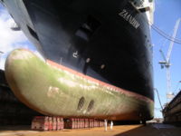
A bulbous bow with a complex shape. The through tunnels contain electric motor-driven propellers to enable maneuvering without the aid of a tugboat. Image courtesy of WikiPedia.
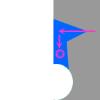
Bow Tunnel Thruster
Include a bow tunnel thruster to give the Iowa even greater maneuverability. This modification, combined with the thrust redirectors on the main propulsion system, should allow the Iowa to be one of the most maneuverable ships in the ocean. The main drawback to this system is that it only functions at low speeds. To address this issue, the refitted Iowa's bow thruster will be fitted with a "shark's mouth" that will allow water that would otherwise pass by the bow to be redirected 90 degrees to the direction of travel. This "shark's mouth" is basically a hatch or valve that can be opened at speed. The water that comes into the valve will be directed downward into the path of the bow thruster. The thruster will then eject the water to either the port or starboard side of the ship. This in turn allows the ship to use the bow thruster to make tighter turns at speed.
The general flow of water into the shark mouth can be seen in this image:
Superstructure Modifications
Meet NATO guidelines for:
- Shock Protection (STANAG 4142, 4137, 4549)
- Nuclear, Biological, and Chemical Protection (STANAG 4447)
- Vital Area Armor Protection (STANAG 4569)
Use Multi-Function Electromagnetic Radiation System (MERS) to provide low-signature capabilities for:
- UHF communications
- LINK 16 Line of Sight (LOS) communications antennas
- Identification Friend or Foe equipment
- Combat Direction Finding Equipment
Applying another lesson from the San Antonio class ships, the Iowa's superstructure shall have a faceted appearance with few right angle structures and few orientations of reflective panels. Doors and hatches shall be flush with the surfaces and the windows are flush without visible coamings (edge of window aperture) and will be fitted with radar reflective screens. All antennas, mast stacks, exhausts, vents, intakes, and other "deck clutter" items will be redesigned to provide low-signature versions. These redesigned systems will be based on work done by the Naval Postgraduate School's Total Ship Systems Engineering design programs. One of the key superstructure modifications will be the use of a miniature version of the Low Observable Multi-Function Stack (LO Stack) Embedded Antennas. The LO Stack will be used to cover vents, air intakes and exhausts. This system can support four satellite systems simultaneously: an EHF TX array, EHF RX and GBS RX array, a UHF array, and an INMARSAT array. All of these antenna arrays will be fabricated out of low-observable composite materials and provide exhaust suppression.
Similar to the San Antonio class ships, the refitted Iowa's deck edges will be bounded by shaped bulwarks rather than lifeline stanchions. These bulwarks will be hollow and double as storage lockers, eliminating locker clutter on deck. These solid rails will use shaping to reflect radar energy away from the ship at an odd angle rather than directly back at the hostile radar antenna. These shaped bulwarks will also provide low RCS protection for the anchor chains on deck. In addition, all exterior equipment will be recessed or flush-mounted where possible, giving the ship a cleaner exterior appearance. Any equipment that cannot be flush mounted (like ladders) shall incorporate shaping features of their own. Another lesson learned from the San Antonio class, the anchor and anchor pocket will be shaped to minimize radar backscatter.
To provide a means of moving heavy loads on the ship, the refitted Iowa will use the reduced radar cross signature hydraulic crane first used on the San Antonio class ships. This crane is rated for 22,000 pounds, and has a 65 foot reach. The San Antonio ships use it to move Rigid Hull Inflatable Boats from the boat valley to the waterline, recover the boats, or load cargo. The newly designed crane utilizes a positive control "Derrick Head" capturing device that affords safe boat operations through Sea State 3 conditions (3-4 feet seas). The boat-handling crane in the center of the ship folds into a clean shape when not in use. This crane, or a version that can lift more weight, will be used for automated loading of gun ammo, missiles, boats, and other cargo. Put one crane each port/starboard in current UNREP position (next to midpoint aft ABL), as well as next to the conning tower.
To increase the protection offered by the ship's deck, the refit process will replace the older teak deck with HY-80 or HY-100 steel taken from submarines that are in Ship-Submarine Recycling Program [SubmarineSteel]. The teak from the deck and use it to line captain's quarters, flag officer quarters, and create seating in mess hall(s). Alternatively if the teak is in good condition, it could be sold off by the Navy to generate some of the funds needed to refit the Iowa.
Bridge Modifications
The extreme overpressure of 16" gunfire and its effect on the bridge have been well documented over the years. In an effort to mitigate those effects, M270 MLRS-carrier style blast shields (horizontal armor slats) will cover bridge windows when firing 16" guns to protect them from the overpressure. These horizontal slats should be powdercoated to protect them from corrosive environments. In addition to these armored slats, the original glass windows will be replaced by the transparent armor currently in use on CVN-76 and CVN-77. This armor, in addition to the armored slats, should allow the Iowa bridge to be fully enclosed while the 16" guns fire. Periscopes containing cameras will be positioned across the top of the bridge and fire control tower in order to provide visual information to bridge crew when the blast shields are in place. The periscope electronics from a Virginia class submarine or the current electro-optical systems should be used as the periscopes for the Iowa bridge.
To provide information to the bridge crew when the armored slats are closed, the Iowa will take advantage of some advances in projection technology to display "false visuals" and status information on the inside surface of the windows. By using smart glass [SmartGlass] and LED based projectors mounted in the ceiling of the bridge, it will be possible for the Iowa's computer systems to provide views of what's going on outside the ship. This is a logical extension of the heads up display systems currently in use on fighter aircraft and attack helicopters. Of particular interest are the results of IBM Corporations Everywhere Displays Project [EDP]. These large screen displays will also provide a method to display course plotting information and sensor contacts while in combat. Note that at the time of initial refitting, the smart glass displays will not be capable of displaying HUD information when the armor slats are open and sunlight is coming into the bridge. Future advances in smart glass technology will likely correct this shortcoming.
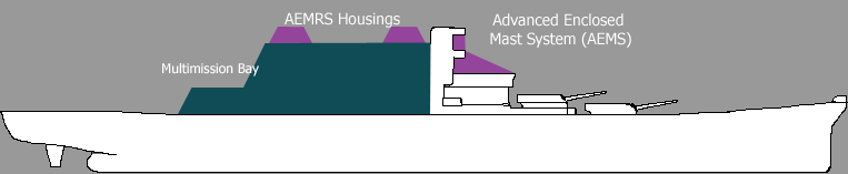
Multimission Bay
This is an expansion of the "sea frame" concept pioneered in the U.S. Navy by the Sea Fighter and the Littoral Combat Ship and the Danish Navy's STANFLEX 300 ships. The "dorsal fin" area (stacks, intakes, the location of Armored Box Launchers) will be replaced with a Multimission bay that accepts various containerized mission packages (packages must fit into containers 8 feet wide, 8.5 feet tall, and 20/40 feet long See [ContainerDimensions]). These are expected to be additional VLS or cannon systems in most cases, but UAV, command, medical, and other variations are all possible [MissionContainerTypes].
The Multimission Bay should offer armor protection at least equivalent to the armored citadel it replaces. Again, this can be done by using HY-80 or HY-100 steel from submarines [SubmarineSteel].
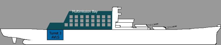
Due to the size of the Iowa, it will be possible to put several levels in the multimission bay. This will allow for increased flexibility when compared to the single-level deck provided on current vessels. The following image shows one possible configuration for placement of the mission containers. This particular configuration shows that 25 custom mission modules could be installed in the bay. (This image should not be taken as correct or final; Detailed calculations are underway to find accurate counts.)
The upper level of the bay gets some sort of cover. Either a garage door style opening to the side or a bomb bay hatch style system. This might be specific to the module that is in the bay. For example, if deploying MQ-8B Fire Scout UAV helicopters, it makes sense to have the bay open at the top and not the side.
Each of the Multimission bay's levels should have overhead crane to maneuver mission modules around the bay. The lower level crane should open into the reactor compartment to allow for reactor refueling or replacement. These cranes will also be able to extend beyond the aft end of the MMB to allow various containerized weapons systems to be installed. In addition, two UNREP cranes will be placed at the aft end of the MMB to expedite the replenishment operations. These cranes will be based on the low profile knuckleboom cranes installed on the San Antonio class ships.
Modular Weapon Mounts
Place eight weapon mounts atop the Multimission Bay, four each port and starboard, which can mount AGS turrets, 5"/62 Mark 45 Mod 4 turrets, NLOS-LS missile modules, ESSM launch modules, VLS modules, SeaRAM and CIWS systems, AMOS decoy launchers, or communications, sensors, and intelligence gathering packages. In addition, the refitted Iowa will convert the remaining 5"/38 caliber gun mounts to the same type of modular weapon mount as found atop the Multimission Bay.
Helipad/Air support
The Iowa currently has approximately 3605 square feet of flight decking. After making some minor changes to the elevation of the aft decking, the refitted Iowa can have a maximum of 14,550 square feet (about 1351 square meters) of flight deck. This is 321 more square meters than the Littoral Combat Ship, which currently has the largest amount of helipad area with 1030 square meters (11,100 square feet) of flight deck. In addition, the removal of Turret 3 and its replacement with an AVLS system allows for even more supplementary flight decking.
This increased flight deck size will allow the refitted Iowa to land, refuel, and rearm all sorts of aircraft, ranging from the navalized Fire Scout VTUAV to the MV-22 Osprey. The refitted Iowa will also match the flight deck performance of the Sea Fighter, whose deck has two helicopter landing spots capable of handling a variety of aircraft up to the size of the H-60-series helicopter. A special deck lighting system has been developed for Sea Fighter using low intensity green lighting around the vessel's edges and helipads. This lighting is particularly effective when using night vision goggles, making landings on the vessel easier than on conventional warships, even at the higher speeds in which Sea Fighter operates. Using the Advanced Lighting System developed for the DD(X), which incorporates the NVG-compatible system in used in the Sea Fighter, will make the Iowa compatible with all sorts of aircraft currently in Naval service.

The refitted Iowa will have armored doors over the former Turret 3 location, primarily to protect the vertical launch system located here. These armored doors effectively raise the level of the afterdeck, and provide multiple function space on the afterdeck while also balancing the ship. Doors open like bomb bay doors (lift to port and starboard) in order to protect RHIBs stored in this area. In addition, a hatch to the 16" magazine autoloader system is located in this area.
This auxiliary space will function as:
- Marine/Sailor physical training area
- Auxiliary flight deck
- Marine ground equipment repair
- RHIB storage area
- General storage area
Sea Fighter - Above the bridge is a small flight operations station with room for only one operator. This glass enclosed station provides an excellent view of the entire flight deck, and allows the operator to coordinate the approach and landing of helicopters, and loading of the vessel's mission containers [MissionContainerTypes], as well as providing visual aid for navigation.
Turrets
All the turrets on the refitted Iowa will have a capability similar to the German Army's PzH 2000 integrated into them. The PzH 2000 turret includes a phased array radar on the front glacis for monitoring outgoing rounds and correcting for windage. Laying can also be automatically provided via encrypted radio links from rear area command. This will allow forward observers from the Marine Corps, Army, and Air Force to automatically send fire mission info directly to the Iowa without intervention from her crew. The front mounted radar system will allow the Iowa's on board computers to correct shell trajectories as needed, again without intervention from the crew.
Turret 2 will be removed from the hull. There is damage to the center gun, and removing it will provide spare weapons for the remaining two turrets. Turret 3 will be moved from it's current location at the rear of the ship to the Turret 2 location in the ship's bow. The Turret 3 location and surrounding crew quarters will then be converted to house both an automatic ammunition handling system and a VLS system based on the Mk57 Advanced VLS. (According to Harpoon Database, each turret weighed 2100 tons, so I'll need to counterbalance it with something else.)
The former Turret 2 will be moved ashore to provide a land-based facility to fill the following roles:
- Training for maintenance personnel
- Testing new automatic shell loading systems
- Testing new propellants
- Testing new shells
- Testing new gun barrels (single piece steel barrels, titanium barrels)
- Testing new gun mounts (titanium, carbon composites)
- Testing new gun control systems
As mentioned in the Helipad/Air Support section, the refitted Iowa will have armored doors over the former Turret 3 location, primarily to protect the vertical launch system located here. These armored doors effectively raise the level of the afterdeck, and provide multiple function space on the afterdeck while also balancing the ship. Doors open like bomb bay doors (lift to port and starboard) in order to protect RHIBs stored in this area.
Turrets 1 and 2 get armored doors in back or top like the M1 Abrams. This will allow:
- Faster at sea rearming (UNREP).
- Provide crew and weapon protection by allowing the force of an explosion to blow up and away or out and away from the ship. (Addresses the safety issue that befell the Iowa in the 1989 explosion of Turret 2.)
- Possibility: Top and back unfold/unhinge to form loading ramps. Put winch/crane equipment on inside surface of turret ramps.
Ammunition blow out panels similar to those on the M1 Abrams tank family will serve to protect the crew and also facilitate the use of automated reloading systems. Increase the amount of armor around the turret barbette to force explosions up and away from the ship.
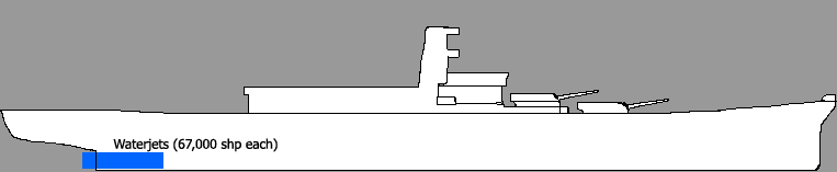
Propulsion/Propellers
The Iowa needed 212,000 shaft horsepower to move along at 33 knots. This is equivalent to 158 megawatts of propulsion energy. After careful consideration of updated fixed pitch propellers, skewback propeller designs, variable pitch propellers, podded propulsion systems, and various waterjets, the refitted Iowa will use compact axial-flow waterjets [rrwj] to provide propulsion for the Iowa. There are several benefits to axial-flow waterjets:
- Efficiency of 90% (or more) - Most of the power put into propelling the ship goes to propelling the ship.
- Increased maneuverability - Waterjets use thrust redirectors instead of rudders to steer the ship. These redirectors allow for increased maneuverability and even allow the ship to stop quickly. This maneuverability is a good thing in a warship.
- Quieter than propeller systems - Waterjets are much quieter than traditional propeller based propulsion systems. This is the reason they're used on modern submarines. Since one of the criticisms of the Iowa is that she's loud, quieting her propulsion down is a good thing.
- Lightweight - This means more tonnage is available to the ship for weapons, sensors, and other payloads. In addition, the use of lighter propeller shafts saves at least 400 tons of weight that was taken up by the shafts needed by the previous propeller system. [PropShaftInfo]
- Reduced strain on engines - This reduces maintenance needs for the engines, which drives down the Iowa's maintenance costs.
- Increased protection and reduced maintenance costs - The waterjets used by the Iowa will have most of their mechanical controls located within the hull of the ship. This removes the need for an external dive team to install and inspect the mechanical controls, which reduces maintenance costs.
- Waterjets are proven in Naval and Coast Guard service. They're used on several Navy and Coast Guard ships, ranging from the Sea Fighter concept vehicle to service auxiliary ships (supply ships).
- The conventional waterjets used on the Iowa will take in a lot of water. This water will increase the weight of the aft of the ship, which in turn will help balance out the loss of Turret 3 and its ammunition.
Finally, using waterjets will eliminate one of the most annoying features of the Iowa: The "jackhammering" effect when running at full speed. This occurred because the forward props sent turbulent water into the aft props. By moving all the waterjets to the same frame in the Iowa's hull, that turbulent water is eliminated.
To get the 158 megawatts of power needed, the Iowa will have to be fitted with at least four Kamewa waterjets. Each of these waterjets will be driven by a single 67,000 HP permanent magnet motor. An additional PMM will be used to provide additional power to the ship for weapons and other tasks. These four waterjets should be sufficient to maintain the Iowa's current 33 knot speed; If desired, and additional waterjet could be installed to raise the cruising speed of the Iowa to the 35 to 37 knot range.
Ship Silencing Information
QuietShip products can reduce noise by up to 70%. In Sea Fighter, QuietShip reduces noise by 15db. Be sure to put this sound-deadening insulation around the reactor compartment to reduce engine noise and the turret barbettes to reduce mechanical noise. In addition to the standard sound isolation practices already in use, the Iowa will have anechoic tiles applied to the external hull. These tiles are in use on the Virginia class submarines where they greatly reduce the noise of the entire ship [AnechoicTiles].
Reduction of sonar self noise over the frequency range of passive capable sonar is one goal of the Navy Ship Silencing Program. The other goal is a maximum reduction in the ship's radiated noise to obtain the best possible counter-detection posture relative to enemy submarines. Unwanted noise can severely limit a ship's overall USW capability, both active and passive. A lack of understanding or inattention on the part of ship's personnel can negate the effect of installed quiet ship features.
Platform noise is that noise generated by own ship other than the sonar system. Platform noise consists of radiated noise and crew generated noise. Control of this noise is the purpose of the shipboard noise control program. Platform noise is a primary concern when operating in EMCON.
Three classes of Sound Isolation Devices
- Resilient Mounts - rubber shock devices used on machinery and piping.
- Distributed Isolation Material (DIM) - rubber type pads used on smaller equipment.
- Flexible Connections - used on pipes and hoses.
Sound isolation devices are most effective when properly matched to machine characteristics and when both the machine and device are properly maintained. Examples of each type of sound isolation device can be seen in the following image. Image and information courtesy Federation of American Scientists.
Power and Propulsion
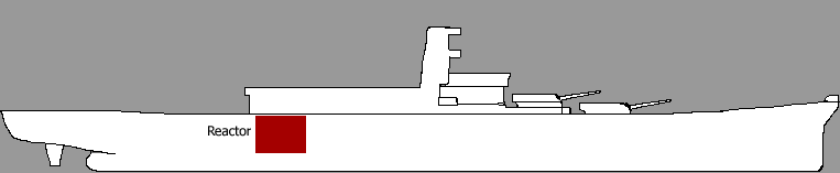
Main Power
After careful consideration and review of the options, the refitted Iowa will make use of two Generation IV Gas Turbine-Modular Helium Reactors (GT-MHR) rated to produce 125 megawatts each. This will provide the Iowa with 250 megawatts of electricity. This new reactor, originally developed by General Atomics under a Department of Energy contract, contains several new construction methods and integrated safety devices that will make it well suited for naval service. The two reactors' gas turbine generators will drive five advanced technology electric motors. [APfHSS] These advanced Permanent Magnet Motor engines will each generate 67,000 HP to drive each of the four waterjets.
Should the GT-MHR not be available for some reason, the Iowa will use either a pair of the Transformational Technology Core (TTC) pressurized water reactors currently in development for use on the Block IV/V Virginia class submarines, or a pair of A5W/A1B reactors planned for use in the CVN-21/Gerald R. Ford class aircraft carriers.
An additional Permanent Magnet Motor will be used to generate additional power for other ship's needs, like hoteling services (life support) and weapons. If desired, this motor can be attached to a fifth waterjet to increase the speed of the Iowa from its current 33 knot maximum to approximately 37 knots.
In addition, as work progresses on the direct conversion of heat to electricity, these systems can be refitted into the Iowa hull with relative ease. This work is being done as a part of the Submarine of the Future effort [SOTF], and is not expected to provide successful technologies until after 2020.
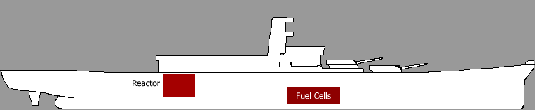
Supplementary Power
The existing Ships Service Turbine Generators (SSTGs) will be replaced with higher capacity, smaller-footprint units capable of generating 1,500 kilowatts. These conventional diesel engines will use the Tactical Power Systems [TPS] developed by Purdue University for the Army. This system creates methane through the controlled breakdown of the crew's food waste to generate power. In addition, once the Waste Power System is perfected, it will be installed on the Iowa. This system is designed to use the plastic packing materials used in shipping goods as the main fuel source for a diesel generator.
There are also some fuel cells under development by Penn State [PennStateFuelCells] that use human waste to produce hydrogen and electricity. These would be good for handling crew's excreted waste, turning a liability into an asset (hydrogen for engines or gun propellant, water for flushing toilets and fire suppression systems).
Though using and storing hydrogen on Navy ships is obviously a difficult and dangerous task, the opportunities afforded by the use of Microbial Fuel Cells that simultaneously clean water, destroy crew waste, and provide potential propellant gas are too great to ignore. By positioning a set of small turbines derived from the M1A2 Abrams main battle tank's Under Armor Auxiliary Power Unit (UAAPU) near the exhaust ports of the microbial fuel cells and burning the hydrogen immediately, the Iowa's exposure to explosive accidents is greatly diminished. By adding a supply of atmospheric oxygen as a safety, any hydrogen can be converted into clean water for use by the crew or in fire suppression tasks.
As hydrogen handling improves, it may be possible for the Iowa to redirect its hydrogen output to another ship in the task force for combustion in their power plant. Alternatively it may be possible to use the collected hydrogen as a gun propellant, as in the Combustion Light Gas Gun.
Power Distribution
The refitted Iowa will have dedicated port and starboard AC and DC power buses. Each of these buses can be cross linked between port and starboard to provide redundancy. In addition, the use of a Zonal Electrical Distribution System to isolate the potential for problems and minimizes the effect on the rest of the ship. The Zonal Distribution System's key advantage over the Radial Electrical Distribution System currently in use is the tiny number of bulkhead compartment penetrations required. In the Zonal system, only the actual power distribution busses penetrate the watertight bulkheads, while a Radial system requires hundreds (or more) of bulkhead penetrations. The lower number of watertight bulkhead penetrations generated by having the busses penetrate the bulkheads, and the loads in each compartment directly attaching to the zonal busses, directly increases the survivability of the ship. Another key benefit is the ability to locate and isolate faults more quickly in the Zonal system. [SeaTentacle]
Combining this with an Integrated Fight-Through Power System (IFTPS) based on the system developed for the DD(X), the refitted Iowa will be able to automatically reconfigure its power distribution system after taking damage. In addition to this change, the Iowa's power distribution infrastructure will be able to be swapped out completely and replaced with a new system based on High Temperature Superconductor (HTS) systems. This system will allow more efficient energy transfer between various ship systems.
Weapons
In keeping with the recommendation of the Submarine of the Future [SOTF] review document, the retrofitted Iowa will make use of several "bomb bay" style modular sections [MissionContainerTypes] to allow the use of a wide variety of weapons and auxiliary equipment. These modules will fit into the space between the outer hull and the inner armor belt. These areas were formerly used to store fuel oil and ballast for the Iowa. These modules currently have dimensions of 30 feet tall (main deck to keel), 10 feet deep (outer hull to centerboard), and 15 feet wide (bow to stern). Each side of the ship can contain 18-20 modules. These dimensions allow a Mk 57 Advanced Vertical Launch System to be installed, as well as several other possible module designs. [ModulePayloads] Alternatively the modules and module bays could be sized to fit a standard shipping container. [MissionContainerTypes] [SUWMissionPackage])
Cannon
The primary mission of the Iowa is to provide shore bombardment capabilities in support of amphibious landings. To that end, a great deal of emphasis is placed on the cannon systems used on the Iowa. The current Mark 7 16" gun, hereafter designated the Mark 7 Mod 0, has served the Iowa class well through its service life. In the time that has passed since the Iowa first put to sea there have been many advances in materials technology and metallurgy which would allow the refitted Iowa to extend her range and reduce her gun maintenance needs. In addition, an ongoing effort shall be made to incorporate the results of the Office of Naval Research's ONR's Advanced Gun Barrel Technologies Program into the creation of new Mark 7 Mod programs. One of the key goals of this program is to increase the lifespan of the barrel by 50% over the baseline.
The first follow-on 16" gun project, designated the Mark 7 Mod 1, will replace the built up gun barrels with a single cast version as the Mark 7 Mod 0 barrels wear out. This will allow the gun to use stronger propellants and possibly provide better barrel life. In addition the use of titanium in the barrels could reduce the weight of the barrel.
Once the use of titanium in the gun barrels has been demonstrated to work, the next 16" gun project will replace the existing 50-caliber barrels with longer versions. The new barrels used in the Mark 7 Mod 2 will be anywhere between 55 and 62 calibers long. These longer barrels will allow the propellant to burn more completely, thereby increasing the amount of energy imparted to the shells as they are fired. This in turn increases the range of the shells that are fired from the 16" guns.
The last 16" gun project, designated the Mark 7 Mod 3, will attempt to replace the steel mounting systems in the turret with versions made from lighter and stronger materials. Potential replacement materials include:
- HSLA steel
- LASCOR steel
- Titanium
- Carbon fiber composite
Due to the use of increased automation and the corresponding reduction in crew size, there will be a lot of space available to store more rounds. This will allow the refitted Iowa to carry at least 50% more 16" rounds than previously.
16 inch Ammunition Propellant System
Opponents of various reactivation proposals have made much of the fact that the original propellant for the 16" guns used by the Iowa class ships was produced and bagged in World War II. This means that the propellant is 60 years old, and it has inconsistent performance which reduces the accuracy and utility of the main guns. To remedy this, a great deal of time and effort would need to be devoted to rehabilitating the propellant so it is fit for service.
The answer to this problem is simple: Don't do it.
Use modern propellants developed for active naval guns and artillery systems to provide the propulsion needed by the 16" guns. There are several of these propellant systems already in use around the world, and more are scheduled to come online in the next three years. One key example is the EX167 propellant used by the DD(X) destroyer's Advanced Gun System, and another is the EX175 propellant used in the Mark 45 Mod 4 five-inch gun. Propellant handling systems have also advanced beyond the silk bags the Iowa has used to this point. Key examples of this concept include the UNIFLEX2 Modular Charge System, the U.S. Army's XM231/XM232 Modular Artillery Charge System which only provides two propellant types, and the German PzH 2000 howitzer's standardized charge system with six different charges which can be combined to provide exactly the power needed and no more.
Both systems store the propellant in plasticized containers that are completely destroyed when fired. This greatly simplifies the handling requirements of the propellant and allows for development of more energetic propellants. Therefore, the Modular Artillery Charge System will be used as the basis for all 16" gun propellant delivery.
The Modular Charge system described above can be combined with the palletized magazine system developed for the AGS which is described below to simplify rearming and other logistical concerns. Changing the system to use a "clip" or "rifle magazine" to hold the propelling charges might work even more effectively.
Theoretical Propellants
Hydrogen based propellant system - This system would take the hydrogen created from microbial fuel cells or split seawater and direct it into "powder bags" that hold the hydrogen under pressure. Sealing the containers puts the hydrogen under pressure. Use an Electrothermal Chemical igniter to ignite the gas and launch the shell.
Secondary Battery Weapons
5 inch guns
The Iowa originally used the Mk 12 5"/38 caliber dual purpose gun. Later 5" guns and propellants have a range increase varying between 45% and 130% as shown in the following table.
| Name | Bore (in) | Caliber | Propellant | Range (yds) | Range Delta | Notes |
|---|---|---|---|---|---|---|
| Mk 12 | 5 | 38 | - | 17,392 | N/A | Assumed to be baseline (100%). |
| Mk 45 Mod 0-2 | 5 | 54 | - | 25,290 | 45.41% | |
| Mk 45 Mod 4 | 5 | 62 | Mk 67 | 25,880 | 48.80% | |
| Mk 45 Mod 4 | 5 | 62 | EX 175 | 40,000 | 129.99% |
The Mk 45 Mod 4 will fire standard 5 inch ballistic ammunition as well as the ERGM and BTERM rounds. The refitted Iowa will happily accommodate these 5" guns in modular weapon mounts, but the main secondary armament is expected to be the Advanced Gun System developed for the DD(X) destroyer.
Advanced Gun System (AGS)
The Iowa will use the Advanced Gun System currently in development to replace the existing 5" guns in low-signature turrets. This will result in the Iowa receiving at least six (6) AGS cannon. As each AGS is almost totally automated, the crew size of the Iowa will be reduced by 14 for each 5" gun that is replaced. This is a savings of 84 crew members total.
The Advanced Gun System is a large caliber, unmanned gun system designed to fire long-range projectiles in support of land attack missions, such as strikes at specific targets or suppressing fire in support of ground troops. The DD(X) design calls for two gun systems with approximately 300 rounds in each magazine, with an additional 320 rounds in an auxiliary magazine. Because the gun system provides supporting fire for land attack, a fundamental mission objective of the DD(X), it needs to be able to quickly and accurately hit a substantial number of land-based targets from a significant distance. The system consists of the mount (the gun together with its housing and movement mechanisms), a fully automated magazine, and a munition known as the Long Range Land Attack Projectile.
AGS on DD(X) will provide a three-fold increase in Naval Surface Fires coverage via:
- Long-Range Land Attack Projectiles, enabling DD(X) to provide 24-hours-a-day, seven-days-a-week fires, even in the most adverse weather conditions;
- Two Advanced Gun systems, delivering 10 rounds per minute each (i.e., 20 rounds per minute per ship);
- Two DD(X)'s can deliver essentially the same firepower as an artillery battalion;
- The ability to meet the Marine Corps' stated fire requirements, a capability otherwise unavailable in the surface fleet; and
- A ship design that allows underway replenishment, allowing an almost infinite ammunition magazine and nearly continuous fire support."
Enclosure IV: Advanced Gun System[2]
Table 11: Performance Parameters Relating to Advanced Gun System
| Performance parameters | Threshold | Objective |
|---|---|---|
| Number of advanced gun systems (a) | 2 | 2 |
| Total ship advanced gun systems magazine capacity (a) | 600 | 1200 |
| Ship personnel (with helicopter detachment) (a) | 175 | 125 |
| Gun ready - time required to execute a mission | 2.5 min. | 1 min. |
| Maximum rate of fire - number of rounds per minute | 10 | 12 |
| Sustained rate of fire - rounds at maximum rate | 300 | 600 |
| Accuracy - distance of impact from target | Classified | Classified |
| Range - distance in nautical miles munition can travel | 63 | 100 |
| Lethality - explosive power of munition | current 155mm | current 155mm |
Sources: U.S. Navy (data); GAO (analysis and presentation). (a) Key performance parameter
AGS has 600 ballistic + 70 LRLAP rounds in magazine, with storeroom of 320 more rounds off of magazine (these shells need to be manually moved). Can sustain fire rate of 10 (formerly 12) rounds/second. Rocket assisted shells have 100 nautical mile range. Fully automated magazine. The biggest drawback to the AGS is that it cannot use existing 155mm ammunition. Its palletized ammunition system is restricted to AGS. This is a major flaw that needs to be overcome. AGS is thought to need about 800 kW of energy to work.
Furthermore, the AGS can fire several consecutive rounds at the same target with varied trajectories so they arrive simultaneously. This Multiple Round Simultaneous Impact (MRSI) capability can be employed against targets up to 75 miles away.
The AGS, as designed for the DD(X), is fitted into a low-signature housing that looks like a trapezoidal shape (gun breech, mount, trunnions) that mates to a rectangular system (hides the barrel). The estimated dimensions of the turret, based on deductive reasoning from available artist's concepts and photographs, are listed below.
| Overall length | 38 feet |
| Barrel shroud length | 12 feet |
| Barrel shroud width | 9.5 feet |
| Gun turret length | 26 feet |
| Gun turret width @ barrel | 9.5 feet |
| Gun turret width @ back of turret | 19 feet |
The AGS as deployed on the Iowa will be able to use the 155mm ammunition in use by Army and Marine Corps artillery units. This allows the Iowa to draw ammunition from friendly forces, and conversely, provide ammunition to those same units in times of crisis.
Other Secondary Battery Weapons
The Iowa will also be able to use modularized versions of the 35mm Mk 44 Bushmaster cannon used on the San Antonio and the 57mm Mk 110 cannon in use on the Littoral Combat Ship family and vessels of the Coast Guard.
With the success of the 155mm AGS, the Navy will examine the use of other Army and Marine Corps artillery systems for conversion and use on Navy ships. The lighter 105mm artillery cannon used by the Marine Corps is particularly interesting because it can offer higher rates of fire to the Navy, which may make it useful in a ship-defense role. The AGS is a good weapon for NSFS, but its size makes it sub-optimal for self-defense purposes.
Among the new technologies now being marketed to the Army is United Defense's variable-volume chamber cannon, called the 105 mm V2C2. In February, United Defense test-fired the V2C2 using a 105 mm round and a 155 mm modular charge. The weapon can be integrated with a 20-ton class combat vehicle or configured as a towed platform, said Jim Unterseher, UDLP's Army program director.
"We believe this cannon system offers a cost-effective 105 mm solution for the Army field artillery," he said.
The variable volume chamber allows the Army to use the M231 and M232 modular artillery charge system that is already in its inventory. That would enable artillery units to employ only one family of propellants for 105 mm and 155 mm systems.
Cannon ammunition types
The flexibility of the cannons aboard the Iowa is directly related to the various ammunition types available for it. To that end, several new rounds will be created for the refitted Iowa. The main feature of the Iowa-class battleships are their 16" guns. In order to maximize the effectiveness of the gun, several new ammunition types will have to be developed. For the purposes of comparison, the original 16" ammunition ranges are shown below as a baseline.
Existing 16" Ammunition
| Elevation (degrees) | AP Mk 8 2700 pound shell (yards) | HC Mk 13 1900 pound shell (yards) |
|---|---|---|
| 10 | 17,650 | 18,200 |
| 15 | 23,900 | 24,100 |
| 20 | 29,000 | 28,800 |
| 25 | 33,300 | 32,700 |
| 30 | 36,700 | 36,000 |
| 35 | 39,500 | 38,650 |
| 40 | 41,430 | 40,600 |
| 45 | 42,345 | 41,622 |
| NOTE: Shows figures for firing a new gun with full charge load. 2700 pound shell can fly 64 yards per pound of D845/NACO. | ||
The existing rounds, with no modifications, have ranges between 9 and 21 nautical miles. This is insufficient for the range requirements given by the Marine Corps, even though those ranges include a stand off distance of 25 nautical miles which the Iowa could probably ignore. By converting these shells to use a base bleed configuration, the range of the shell can be improved by up to 30%. Using the figures above as a baseline, the base bleed versions of the existing ammunition have the ranges shown in the following table.
| Elevation (degrees) | AP Mk 8 2700 pound shell (yards) | HC Mk 13 1900 pound shell (yards) |
|---|---|---|
| 10 | 22,945 | 23,660 |
| 15 | 31,070 | 31,330 |
| 20 | 37,700 | 37,440 |
| 25 | 43,290 | 42,510 |
| 30 | 47,710 | 46,800 |
| 35 | 51,350 | 50,245 |
| 40 | 53,859 | 52,780 |
| 45 | 55,048.5 | 54,108.6 |
| NOTE: Shows figures for firing a new gun with full charge load. | ||
This information shows that making this simple conversion to the existing shells increases their maximum range from around 20 nautical miles to approximately 26 statute miles. Though this still falls short of the 97 nautical miles desired by the Marine Corps, it is still improvement.
Converting the shells even more to use an Electrothermal Chemical (ETC) propellant ignition system derived from work the U.S. Army is doing to improve 120mm cannon performance has the potential of increasing gun performance, especially range, by up to 50%. In 1997 Israel had created an ETC system that increased gun range by 18%. BAE Systems has created a 120mm cannon with an ETC igniter that has improved the range of the gun by 30%. The following table shows the 50% range increase applied to the baseline gun performance - no base bleed shells.
| Elevation (degrees) | AP Mk 8 2700 pound shell (yards) | HC Mk 13 1900 pound shell (yards) |
|---|---|---|
| 10 | 26,475 | 27,300 |
| 15 | 35,850 | 36,150 |
| 20 | 43,500 | 43,200 |
| 25 | 49,950 | 49,050 |
| 30 | 55,050 | 54,000 |
| 35 | 59,250 | 57,975 |
| 40 | 62,145 | 60,900 |
| 45 | 63,517.5 | 62,433 |
| NOTE: Shows figures for firing a new gun with full charge load. | ||
So the ETC system alone increases the range of the standard Mk 8 and Mk 13 shells from approximately 13 nautical miles to a maximum of 31 nautical miles. For an even greater improvement, the ETC igniter can be combined with the base bleed shell. The following table shows the theoretical performance of this combination.
| Elevation (degrees) | AP Mk 8 2700 pound shell (yards) | HC Mk 13 1900 pound shell (yards) |
|---|---|---|
| 10 | 34,417.5 | 35,490 |
| 15 | 46,605 | 46,995 |
| 20 | 56,550 | 56,160 |
| 25 | 64,935 | 63,765 |
| 30 | 71,565 | 70,200 |
| 35 | 77,025 | 75,367.5 |
| 40 | 80,788.5 | 79,170 |
| 45 | 82,572.75 | 81,162.9 |
| NOTE: Shows figures for firing a new gun with full charge load. | ||
So in theory the maximum range of the refitted conventional shells increases to about 46 statute miles. This is a shade under 40 nautical miles. If the stand off distance of 25 nautical miles is ignored by bringing the Iowa in closer to shore, this combination of existing WW2-era propellant, and ETC igniter, and base bleed shells meets the near term need for range quite handily.
It is important to remember that these figures assume a full load of 660 pounds of D845 propellant. It is also important to note that this propellant is over 60 years old at this point and will not be used in the refitted Iowa because of improvements in propellant technology. These newer propellants in use by the Navy will allow for increased range without requiring any special modifications.
Improved conventional ballistic rounds
Based on advances made in field artillery by the U.S. Army and Marine Corps, a series of improved 16" shells will be created. These shells will take advantage of better ballistic shaping, particularly "boat-tailing", to increase the range of the shells. The goal is to improve the range of the shell without requiring expensive rocket assistance. This shall keep the costs of the shell down, and still provide American Marines and Soldiers with the long range fire support required for amphibious assaults.
These rounds, like all of those used in the refitted Iowa, will use the ETC igniter and improved propellants to increase their range.
Cutlass: GPS/INS guided rounds
Based on both the XM982 Excalibur/Trajectory Correctable Munition round developed by the U.S. Army and Sweden, the Extended Range Guided Munition (EGRM) developed for the AGS, and the XM1156 Precision Guidance Kit currently under development, this 16" shell is tentatively codenamed "Cutlass." The Cutlass shell will offer the following advantages over the current 16" shells:
- GPS guidance allows more accurate strikes.
- Rocket assistance allows increased range.
- CEP of less than 50 meters.
Antiaircraft and Antimissile (AHEAD/ABW)
This is inspired by the Lockheed-Martin Millennium Gun's AHEAD (Advanced Hit Efficiency And Destruction)/ABW (Air Bursting Weapon) round. Each 35mm shell has 152 tungsten pellets that explode out in a conical pattern. These pellets tear up airframe control surfaces, damage electronics, and occasionally detonate warheads. A version of these rounds have been developed for use in the Bushmaster series automatic cannon, and they have been used very successfully in tests against airborne targets and ground targets (with various degrees of armor protection).
More information is available from:
- 30 mm x 173 ABM / PMC 308 round info: http://www.rheinmetall-detec.de/index.php?fid=1528〈=3&pdb=1
- 35 mm x 228 AHEAD round info: http://www.rheinmetall-detec.de/index.php?fid=1533〈=3&pdb=1
Multiple Warhead Shell
The Extended Range Guided Munition (ERGM) developed for the 5 inch gun and the Long Range Land Attack Projectile (LRLAP) under development for the 155mm (6 inch) Advanced Gun System (AGS) are far smaller in diameter than the main 16" cannons on the Iowa. This means that multiple smaller rounds can be placed in a single saboted shell casing. This allows a single shell to attack multiple targets simultaneously, or a series of strikes on a single target. By using these multiple warhead shells, the Iowa can effectively simulate the gunfire support of several smaller surface combatants, including the Multiple Round Simultaneous Impact (MRSI) of the DD(X).
SADARM Round
A 16" shell that uses the Sense and Destroy Armor (SADARM) submunition payload defined for the M898 155mm artillery round. A total of 31 SADARM submunitions can be carried by the 16" shell body. The side view only shows 13 submunitions because only two of the three strings of six are shown.
NOTE: The shell dimensions shown here are for a Mk 13 High Capacity shell. Designing a new shell as a dedicated SADARM carrier could theoretically carry more.
Thermobaric Round
This 16" shell is based on the work done for the AFRL GBU-43/B Massive Ordnance Air Blast (MOAB). This shell is centered in either a standard Mk 13 High Explosive or an Improved Conventional Ballistic Shell Body. The MK 13 body will be filled with 2273.25 cubic inches of H6 explosive. At 1.35 times the power of TNT, H6 is one of the more powerful explosives used by the U.S. military. H6 is an explosive combination of RDX (Cyclotrimethylene trinitramine), TNT, and aluminum. H6 is typically employed by the military for general purpose bombs, and is an explosive composition which is produced in Australia. H6 is a widely used main blast charge filling for underwater weapons such as mines, depth charges, torpedoes and mine disposal charges. HBX compositions (HBX-1, HBX-3, and H6) are aluminized (powdered aluminum) explosives mainly used as a replacement for the now obsolete explosive known as torpex. HBX-3 and H6 have lower sensitivity to impact and much higher explosion test temperatures than torpex.
Sub-Caliber SABOT round
Based on the work done for the 13-inch diameter EX-148 round. This was developed in the late 1980's and early 1990's. Prototypes purportedly had a range of 70,000 yards (39 miles), without base bleed or other range enhancers. In addition, the Navy test-fired 280 mm (11 inch) shells designed for the M-65 "Atomic Cannon" from the Mk 7 cannon. The rounds weighed 745 pounds (835 pounds with sabot), and launched with a muzzle velocity of 4600 feet per second, resulting in a range of 100,000 yards (56 miles). This was without the use of base bleed or any other modern range improvement techniques or technologies.
RAMJET/SCRAMJET Rounds
Building on the information in the following patents as well as the Alliant Techsystems Very Long Range Munition - Air Breather (VLRM-AB) [VlrmAB] 155mm round, the work done by Denel on the M9703A1 V-LAP rounds [Vlap], and the work the U.S. Army is doing with 120mm RAMJET tank ammunition, a new solid-fuel SCRAMJET round will be deployed aboard the refitted Iowa. A notational image of the shell is shown below. This round will use the GPS/INS guidance system of the Cutlass round. In addition, the use of SCRAMJET engines will allow the shell to reach impressive ranges. From various unclassified sources, this range could be in excess of 500 miles. Combining the range of this shell with the rapid-fire capability of the 16" guns and the precision of the GPS/INS guidance system will allow the Iowa to provide twenty-four hour a day, all weather fire support for U.S. forces.
The following patents contain a great deal of information about the design principles that would allow such a round to be created.
| Patent Number | Title | Notes |
|---|---|---|
| 4,428,293 | Gun-Launched Variable Thrust Ramjet Projectile | Shell design |
| 4,539,911 | Projectile | Shell design |
| 5,363,766 | Ramjet Powered, Armor Piercing, High Explosive Projectile | Shell design |
| 5,485,787 | Gas Gun Launched Scramjet Test Projectile | Shell design |
| 5,513,571 | Airbreathing Propulsion Assisted Gun-Launched Projectiles | Shell design |
| 5,853,143 | Airbreathing Propulsion Assisted Flight Vehicle | Shell design |
| 7,051,659 | Projectile Structure | Shell design |
| 5,063,826 | Armament System | Cannon modifications |
| 5,431,106 | Release of Daughter Missiles | Submunition deployment |
| 5,657,025 | Integrated GPS/Inertial Navigation Apparatus Providing Improved Heading Estimates | Guidance System |
There are also several documents available from DTIC that may be relevant to this shell, in particular:
- ADD016458 - Solid Fuel RAMJET Composition
- ADA196755 - Aerodynamics Analysis of Solid Fuel RAMJET Projectiles
- ADA318443 - Experimental Demonstration of a 120-mm RAM Accelerator
- ADA318454 - Experimental in a 120-mm RAM Accelerator at Elevated Pressures
Secondary Battery Ammunition Types
All of the existing 155mm artillery types currently available to the U.S. military shall be used by the refitted Iowa's secondary battery. Several of the ammunition types created to support the Mark 7 16" gun will be re-engineered to be used in the secondary battery guns. This effort will include thermobaric, air-bursting/AHEAD shells, and RAMJET/SCRAMJET rounds.
For example, the EX171 LRLAP (Long Range Land Attack Projectile) has a maximum range of 80 nautical miles (92 miles), and warhead and rocket booster combined are 88 inches long. The 155-mm LRLAP round carries a 24-pound warhead. This weapon is designed for use in the AGS.
Possible Future Cannon
Electro-Thermal Chemical Guns - A technology being explored for the Army's Future Combat Systems NLOS-C looks promising. And it uses existing propellants and shells, so it's an evolution of existing technologies. In 2001, BAE Systems showed a 30% muzzle energy increase in a 20mm cannon. The ETC gun uses a captive bolt of plasma to ignite conventional propellant. This plasma, essentially a miniature bolt of lightning, causes the propellant to burn more rapidly and more completely which fires the shell at higher muzzle velocities.
Light Gas Gun - A technology that slams a propelling slug against the back of a shell by slinging the slug through hydrogen, which is less dense than atmosphere. This results in more power going to the shell.
Combustion Light Gas Guns - A combustion light gas gun (CLGG) uses low molecular weight gas as propellant. The gases are ignited, burn, expand and propel the projectile out of the barrel with higher efficiency relative to solid propellant. The principal is similar to a Light Gas Gun (LGG). A working 155mm prototype has been developed for the Navy by Utron Inc. [FutureCannon]
A less-radical example of improved cannon performance can be seen in DTIC document ADA322875 "Use of Electromagnetic Coil Launcher to Increase Muzzle Velocity of Conventional Cannon." Assuming the performance gains can be duplicated, this hybrid weapon could be used to develop doctrine and tactics applicable to the follow-on EM weapons in development for the Navy.
Missile Systems
To recover some of the $11 billion invested in the DD(X) program, the refitted Iowa will make use of the Mk 57 Advanced VLS systems [AvlsInfo]. By placing launchers in the spaces between the outer hull and armored citadel that used to hold fuel oil or were left as voids, 25 launchers could be mounted on each side of the ship. This sacrifices the flexibility of the side-mounted combat modules in favor of large missile load. Tentative placement of the peripheral VLS systems is shown in the next image.
Placing 25 VLS systems along each side of the ship allows the Iowa to have 100 individual launch positions (also called cells), for a total of 200 launch cells. This means that the refitted Iowa will have more launch cells on one side of the ship than is planned for the entire Zumwalt-class destroyer with its 80 launch cells. Placing the VLS systems along the outer edge of the hull behind Turret 2 also shields them from the tremendous overpressure generated when the 16" guns fire.
In addition to the main PVLS systems, the Turret 3 barbette and former crew quarters around it are going to be replaced by Advanced Vertical Launch Systems (AVLS) for even more missile firepower. A total of 36 Mk 57 AVLS launch systems will be placed in this area. This rear missile deck provides an additional 144 individual launch cells for the Iowa's tactical officers. (The individual launch systems are not shown in the following image, only the general missile deck placement.) This large missile pack also counteracts the weight lost by removing Turret 3 and its supporting armor.
Between the peripherally-mounted VLS systems and the VLS systems mounted in the former Turret 3 position, the Iowa will have a total of 86 MK 57 VLS systems providing 344 cells capable of launching any missile in the U.S. Navy inventory. This is 430% of the missile load of a Zumwalt-class destroyer. These missile launch systems weigh a total of 1445 tons.
In addition, two of the AVLS missile cells can fit into a 40 x 8 x 8.5 foot container. Put a pair of cells in the container with power connection, exhaust venting system, etc. The containers can then be placed either horizontally in the Multimission Bay or loaded into the traditional VLS configuration. Loading them into the Multimission bay allows them to take the place of the Armored Box Launchers that have been retired from Naval service.
Splitting the AVLS module into four separate missile tubes allows the individual launch tubes to be placed into the four foot void space between each frame between the Iowa's inner armor belt and outer hull without cutting the ship frames. This will insure that the hull's integrity won't be compromised by inserting full size PVLS cells. Of course not using the full sized modules derived from shipping containers defined above severely limits the adaptability and flexibility of the Iowa, but this increased missile load makes the Iowa an even more fearsome warship.
Each launch cell will be 28 inches deep and 28 inches wide, larger than the existing Mk 41 VLS system launch cells. Since the size of the cells has increased, it may be possible to make a multiple missile launch canister. It appears that with the increased VLS cell size, multiple missile packages holding two, four, or nine missiles can be used. The Mk25 quad pack ESSM launcher for the ESSM used in the Mk 41 VLS is an example of this.
Dual Pack (13" diameter)
- SM-2 (Standard Missile family; RIM-66, -67, -156, -156B, and -161)
Quad Pack (10" diameter)
- RIM-162 Evolved Sea Sparrow (ESSM) family
- Joint Strike Missile - a 10" cruise missile developed from a joint Norwegian-Australian Navy program called Naval Strike Missile.
- SM-2 Standard Missile - folding wings and control surfaces allow the VLS cell to hold more missiles than would otherwise be possible.
Nine Pack (7" diameter) - These missiles will be used mostly for surface defense against small boat threats, but can be used against airborne targets as well as heavier surface ships.
- NLOS-LS missiles
- AGM-114 Hellfire family
In addition, several new missile payloads will be implemented for the various cruise missiles carried by the Iowa. These payloads will be distributed across the entire fleet. These new payloads include:
- Thermobaric
- BLU-108 submunitions (IR guided antiarmor munition) [SensorFuzedWeapon]
- SADARM
The major drawback to all VLS systems is their need to have the carrying ship return to port to reload the VLS cells with new missiles. To address this shortcoming, the refitted Iowa will use the cranes and pully system in the Multimission Bay to move missiles from standard shipping containers into the VLS located at the Turret 3 location. This system is not expected to reload every AVLS cell, but it will be able to reload 25% of the cells closest to the MMB. If successful, the VLS UNREP capability will use the knuckleboom crane from the San Antonio class ships to reload the VLS cells.
Torpedo Systems
Instead of using a deck-mounted torpedo launcher, the Iowa will use the VLASROC missile as its main anti-submarine weapon. In addition, a special Multimission Bay module will be created by inserting submarine style torpedo launchers into standard commercial containers. These modules turn the Iowa into a large Anti-Submarine Warfare platform.
Though these are the primary anti-shipping torpedo for the U.S. Navy, torpedoes are not expected to play a major role in the various missions undertaken by the Iowa. The main close-in anti-submarine weapon for the Iowa will be the Anti-torpedo torpedo (ATT).
Antitorpedo torpedo (ATT)
Derived from the Common Very Lightweight Torpedo (CVLWT) EDM-2 developed under FY07 PE0603506N. It's 6.75" inches in diameter and 105 inches long. Mount two ATT launchers in the stern of the ship, one to each side of the Nixie mount in low profile turrets in the aft 40mm gun tubs, to destroy wake-homing torpedoes. These tubs are 17.5 feet in diameter, and in theory the turret can keep 20 ATT's in a ready-to-fire state. Actually, put 20 ATT's back to back (<-- -->), for a total of 40 ready to launch. Then put a second layer of ATT launchers on top of this layer, mounted at right angles to the lower level. This means that the ATT's will point in all the cardinal directions. The image below isn't to scale, it only shows the configuration of ATT's.

In addition to the two ATT launchers located at the stern of the ship in the aft 40mm gun tubs, an ATT launcher will be placed in the 40mm gun tubs to either side of the bridge. This will provide defense against torpedoes coming in from the Iowa's flanks. Current Navy plans indicate that the ATT will form the basis for the VTUAV-launched Compact Rapid Attack Weapon (CRAW). With this in mind, additional ATT's will be stored for use on the Fire Scout drones embarked on the Iowa.
Defenses
Passive Defenses (Armor)
In addition to the standard armor already in place on the Iowa, advances in armor technology (like Chobham armor) will allow for improved protection. For the Iowa refit, depleted uranium armor plate will be used extensively to protect crew quarters, bridge, combat information center, and reactor spaces. In addition, the refit progress will replace the non-ballistic teak deck with armor made of depleted uranium and HY-80 steel from the hulls of submarines in the Ship-Submarine Recycling Program. This armor protection should meet or exceed the NATO Vital Area Armor Protection requirements outlined in STANAG 4569. Depleted Uranium (DU) is used because it is very dense; at 19050 kb/m^3, it is almost 70% more dense than lead. Because of its high density it can also be used in armor, sandwiched between sheets of steel armor plate. Using so much depleted uranium in the refit also addresses the need for the U.S. military to get rid of the large amounts of uranium that would otherwise have to be very carefully destroyed by the Department of Energy.
In addition to these typical armor products, the interior surfaces of the ship's hull and armored citadel will be coated with a layer of Rhino Linings USA's Rexar polyurethane to provide an additional level of soft protection. The lining has been used extensively by the U.S. Army to protect its lighter vehicles and buildings. The coating will provide a solid membrane that can stretch to the back of the armor used in the Iowa. This membrane can flex with the shock of incoming fire, and will prevent shrapnel from flying through the ship and impaling sailors. [RhinoLining]
The Peripheral Vertical Launch System to isolate each MK 57 VLS four-cell module to achieve maximum survivability in the event of enemy engagement. In addition, the missile payloads of each VLS module will serve the Iowa as reactive armor, deflecting the energy from an enemy antiship missile up and away from the Iowa hull.
Electronic Counter Measures
The standard AN/SLQ-32V5 ECM suite shall be placed on port and starboard side of the antiaircraft deck of the fire control tower, as well as one near the aft end of the Multimission Bay. These systems will also transmit their detection information to the Combat Centers. When new follow-on ECM systems are developed and deployed, they shall replace the SLQ-32 series systems. The most likely replacement is the AN/SLY-2 Advanced Integrated Electronic Warfare System (AIEWS).
In addition to the standard ECM suite, the AESA radar system that forms the core of the Iowa's sensor suite will be able to blind incoming missiles. The AESA radar system in the F-22 Raptor can blind incoming missiles, so the same capability should be available to the refitted Iowa. This will obviously reduce the amount of incoming fire that the decoy launch systems and point defense systems need to counter.
Decoy Launch Systems
The MK36 SRBOC has six tubes, four mounted at 45 degrees and two at 60 degrees. Each tube holds one type of decoy round, and each tube can be activated simultaneously. This system has been standard equipment on U.S. Navy vessels for several years, and has served very well. There are some drawbacks to the system however:
- System only has six decoys
- Once fired, the system must be reloaded manually
- Decoys must be selected ahead of time, which means they cannot be tailored to specific threat
- System is not well suited for use in a low-observable housing
- Extremely short range
- Exposes crew to enemy fire
With these thoughts in mind, it seems that the logical replacement is the adaptation of a system like the Marine Corps Dragon Fire II automatic mortar or the Advanced Mortar System (AMOS). Though the AMOS doesn't allow six decoys to be launched simultaneously, there are multiple offsetting benefits to using it:
- Turreted system allows decoys to be launched in any direction
- Turret is already designed to use low-observable housing
- Greater ranges than the SRBOC
- More flexible than the SRBOC launcher as they are able to launch any 120mm mortar round
- Navalized version for patrol boats already exists
- The AMOS mortar has also been selected as a competitor for the Army's FCS Non-Line-of-Sight Mortar (NLOS-M) system, so parts procurement will be easier
- Decoys are held in magazines so a specific threat can be met
- Breech-loading dual-tube mortar system that launches one round every seven seconds (26 decoys per minute)
- System is totally automated
- System can be activated automatically by Ship Self Defense System and other control functions
In addition to launching decoys, the Navy could create modern "depth charges" for surface vessels to fight underwater threats like submarines and mines by adapting existing mortar rounds. Using existing mortar rounds would also provide another defense against small boats.
The only real downside is that the mortars use tubes that are 120mm in diameter, while most of the decoys are 130mm in diameter. It's unlikely that a whole new class of decoys using the smaller size will be developed, so the system will need to be reengineered to use a larger diameter barrel. To use traditional mortar rounds in the larger barrel, a saboting system or other adapter is needed.
To increase the Iowa's survivability when dealing with submarine threats, the AN/WLY-1 Acoustic Countermeasures system currently used on Ohio-class subs will be modified and installed. This system will allow the ship to launch three-inch diameter acoustic decoys to lure incoming torpedoes away from the ship. This system may also allow the Iowa to deploy sonobouys of its own, rather than relying on other ships and aircraft to deploy them. Even if the Iowa is not able to take advantage of the sonobouys it deploys the other vessels in the battlegroup should be able to use the information to defend against submarine threats.
Decoys
The automated decoy launch system used on the Iowa shall be able to launch each of these decoys, which the MK 36 SRBOC system can launch:
- Standard chaff
- Sea Gnat (long range chaff)
- Torch (Infrared decoy)
- Mk 53 Nulka decoys
- Giant IR decoy (developed by private venture) http://www.valleyassociates.com/store/showproduct.aspx?productid=589&categoryid=92
- Bullfighter RF/IR decoy (developed by private venture) http://www.valleyassociates.com/store/showproduct.aspx?productid=587&categoryid=92
- Siren decoy (developed by private venture)
Most of the decoys listed previously are intended to combat anti-ship missiles. In addition to these, several other decoy systems shall be employed on the Iowa to counter submarine threats. The standard AN/SLQ-25 NIXIE Torpedo Countermeasures Transmitting Set will be updated to the latest version and used as the primary anti-torpedo transmitter, until its replacement is ready. The AN/WSQ-11 Torpedo Defense System (TDS) will replace the Nixie system, incorporating the functions offered by that hardware, as well as providing the Tripwire towed sensors and processors to detect threat torpedo and provide launch orders for the associated Anti-Torpedo Torpedo (ATT) All-Up-Round (AUR) countermeasure. The AN/WSQ-11 is planned for installation on large deck ships, like carriers, amphibious assault ships, fleet resupply vessels, and selected DDG-51 Class ships lacking a towed sonar array.
Point Defense Systems
Naval version of XM101 Common Remotely Operated Weapon Stations (CROWS) for using XM307 and XM312 weapons (or M2 Browning, MK19 40mm, M240B 7.62mm and M249 SAW). Another possibility is to use Rafael weapon system called Typhoon that does the same thing and it's already in use on ProtectorUSV, so re-engineering it shouldn't be too difficult. Another possibility is to use the Mk 88 mounting with 25-mm Mk 38 Bushmaster cannon or 30-mm Mk 44 Bushmaster II cannon.
CROWS can traverse 360 degrees and go 60 degrees up and 20 degrees down. The technology used on the CROWS is a variation of the remote-controlled crew-served weapons system already used on combat vehicles like the Bradley fighting vehicle and the M1A1 Abrams tank. The system includes a 15" color monitor with video from cameras (daytime) and thermal imaging (night). Both use laser range finders which allows the gunner to zoom on targets, lock onto them, and maintain the lock while vehicle is in motion. The camera and weapon can be used together or separately. The camera allows the gunner to look one way while the weapon points in another. With all the features used properly the weapon can be used at 98% accuracy while the vehicle is in motion and the enemy is on the run. The weapon is smart enough to know the vehicle's movement, the Earth's movement, and the enemy's movements.
These automated turrets will be tied into the Combat Centers and allow the crew to detect, identify, and engage various threats when larger weapons are not appropriate. In addition, these turrets will be integrated into the ship's self defense systems, serving as a last line of defense against incoming airborne threats like missiles and aircraft.
Close in Weapon Systems
Though the Phalanx CIWS has served the U.S. Navy well since its introduction, there is some room for improvement. The refitted Iowa will take advantage of an improved CIWS system. There are several limitations to the Phalanx CIWS:
- like all gun-based antimissile systems it cannot engage more than one target at a time
- the limited range of the cannon provides an extremely limited engagement time
- the cannon's 20 mm shells may lack sufficient mass to actually divert a missile even after it's destroyed, meaning the missile body will hit the ship
To overcome these restrictions, several changes will be made to the Phalanx system. The most obvious of these changes is the integration of a pair of SeaRAM/RIM-116 launchers on the Phalanx CIWS system's main chassis. These launchers are slaved to the pitch of the gun system, so as the gun elevates and depresses, the missile launchers elevate and depress to match.
The Rolling Airframe Missiles have a range of 4.5 miles, providing an extended engagement envelope for antiship missiles launched at the Iowa. The missiles can also launch against several targets rapidly, and their warheads are effective against incoming missiles, aircraft, and small boat threats.
To provide a backup capability for the missile systems, the GAU-12 20mm cannon currently used in the Phalanx will be removed and replaced with either a 25 or 30 mm Bushmaster cannon firing air-bursting AHEAD rounds. These rounds are electronically programmed by the cannon to detonate at a specific range and altitude when fired. When the shells detonate they scatter at least 152 tungsten projectiles in the path of the incoming threat, destroying or severely damaging it.
Archerfish
Archerfish is a single shot mine disposal system that is operated from both ships and helicopters. Fiber-optic guided, the Archerfish acquires the target by activating its own short range sonar and video link enabling the operator to accurately position the neutraliser to the threat mine and detonate it with it's directed energy warhead. Archerfish negates the requirement for a large, expensive MCM ROV and is up to 4 times faster at clearing mines. Archerfish has been selected as the common neutralizer for the U.S. Navy. When the Iowa class was designed in World War II, the shipyards also included some anti-mine capability in the form of paravanes. If these can be found, they might serve the refitted Iowa well as a launching platform for the Archerfish mine disposal system. The paravanes would have to be deployed and retracted with no intervention from the crew to be effective.
C3I Systems (Sensors, Command)
Integrated technology solutions that embody multi-functionality and relatively small footprints should take precedence over other component alternatives. One key example of this is the Advanced Multi-Function RF System (AMRFS). This system provides the capability to integrate radar, communications, and electronic warfare functions into a common set of RF apertures capable of supporting multiple simultaneous beams. This allows the functionality in use to be selected via software rather than by individual hardware components. This system is currently under development at the Office of Naval Research, but it is a derivative of several other more mature programs including the the SPY-3 radar, the DD(X) Dual Band Radar, the Combined Antenna System, and the SLQ-32 family of EW suites. [SeaTentacle]
AMRFS radar function shall be an active phased array X-Band radar designed to meet all horizon and volume search and fire control requirements and provide missile guidance, including mid-course guidance and terminal homing. This radar should have SPY-3 functionality as its baseline, and is essentially the SPY-3 radar. It shall have a detection range of at least 70 kilometers against anti-ship missile threats. It will provide automatic detection, tracking, and illumination of low-altitude threat missiles in the clutter-filled littoral environment. For this reason, superior clutter rejection will be required.
AMRFS communications functions include satellite communications, both commercial Ku-band and military DSCS (X-band), and line of sight communications like the Common Data Link (CDL, TCDL) in both the Ku- and X-bands. The AMRFS shall be housed in a single mast enclosure that also supports reduced radar cross section, which also reduces manning requirements and lifecycle costs.
Since the functionality of the system will be defined primarily through software, it will be possible to dynamically reallocate the functions of the AMRFS depending on the situation. If volume search functions are not needed, then additional fire control resources become available, or communications bandwidth increases.
The Navigation radar system will be an S-band radar that assures target detection in adverse weather conditions where X-band radars are affected by sea or rain clutter. In addition, the navigation radar will provide a signature comparable to commercial vessels.
Sensor Suite
Derived from information in [SeaTentacle] and [JointAccess].
- Multifunctional Radar
- Electro-Optical System
- IR Search and track system (IRST)
- Volume Search Radar
- Navigation Radar
- Mine Detection and avoidance system.
EW Suite
Derived from information in [SeaTentacle] and [JointAccess].
- Radar Warning Receiver
- Laser warning receiver
- Missile approach warning system
- Decoy system
- IFF system
Communications Equipment
In the refitted Iowa the various communications and computing systems will be physically stored in industry-standard 19" and 24" rackmount enclosures. This will ease procurement and allow contractors and vendors to operate from common physical specifications, which reduces development cost. These enclosures shall be integrated into the superstructure of the ship. Ideally they will be made of carbon fiber or another lightweight synthetic compound to save weight.
Support for all the standard ship-to-ship and ship-to-shore communications systems that have been used on U.S. Navy vessels will be included. This does not mean that the previous systems will be installed. The refitted Iowa will make use of multiple function communications systems and antennas that are defined via software rather than a series of hardware antennas. This will allow the ship to communicate over a variety of frequency ranges and add a variety of capabilities.
With the removal of the steam turbines and boiler engines from the Iowa's hull, large amounts of space are freed up for other uses. One key use for this space will be the installation of command systems that can provide the ability to command amphibious landings and theater-wide operations. Thus the ship will function not only in the fire-support and combat roles, but in the role of a command ship as well.
To expand its communications and command range, the Iowa will also make use of sensor platforms based on the AN/SLQ-49 "Rubber Duck" decoy. These floating buoys were originally developed to launch chaff and flares from a disposable sea-going launch platform. The new sensor platforms will replace the launchers with radar and sonar systems to detect enemy forces. These platforms will also use the communications gear first pioneered for the Army's FCS Intelligent Munitions System to communicate its findings to nearby Navy vessels. The Iowa and members of her battle group will be able to deploy large numbers of these floating sensors to provide surveillance support.
By using a derivative of the Zeroconf wireless network configuration protocol, these Rubber Ducks can be brought under the command of the Iowa's control systems. Future enhancements to the system could include the deployment of IMS-style munitions, decoys, and daylight and night vision cameras. A flock of these ducks could surround suspect shipping, preventing it from leaving the area undetected.
Sonar Systems
Use the Conformal Acoustic Velocity Sensor (CAVES) low-profile array technology and Light Weight Wide Aperture Array (LWWAA) sonar developed for the Virginia class submarines to provide antisubmarine capabilities to the Iowa. These conformal arrays replace a traditional large spherical array with smaller, fitted planar arrays. These arrays are expected to be much cheaper to produce and deploy, as well has having reduced maintenance costs. These conformal arrays can be placed anywhere on the hull, which provides improved ranging and detection capabilities. In addition to reduced cost and better fit, they can be installed without making any changes to the ship's interior layout. Only a few more cables need to be run to the CIC and sonar stations. These arrays can also be fed into existing sonar processors like the AN/SQQ-89 and near-term sonar processors like the system under development for the Zumwalt-class destroyer.
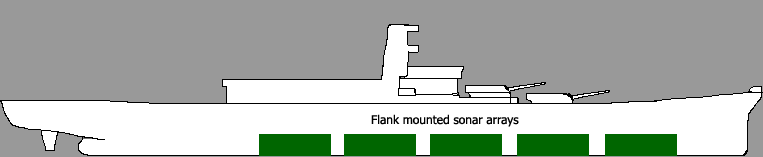
The CAVE arrays mounted on the Iowa's improved bulbous bow will be used to provide early mine detection and avoidance capabilities by feeding information into the AN/AQS-24 high-resolution real-time sonar processor. The information gathered by the sonar system for mine-avoidance will be automatically directed into the Voyage Management System and Electronic Course Planning navigation systems.
The refitted Iowa will use the Integrated Undersea Warfare capability pioneered by the Zumwalt-class destroyer. The IUSW incorporates two types of sonar arrays in one automated system. The high frequency sonar provides in-stride mine avoidance capabilities, while the medium frequency sonar optimizes anti-submarine and torpedo defense operations. The use of sophisticated target algorithms better enables the Zumwalt Destroyer to engage enemy submarines and, at the same time, minimize crew headcount requirements. This IUSW suite shall include the basic functionality of the AN/AQS-24 sonar system, which offers real-time sonar high-resolution images to detect, localize and classify both bottom and moored mines. The system also includes a laser that provides positive visual identification of objects and improved sonar resolution.
For maximum effectiveness, all Iowa noises shall be recorded and the sonar processor will be programmed to ignore them. This should include firing weapons, turret traversal, cannon loading, reactor and generator noise, etc.
Radar Systems
Replace existing radar antennae with Advanced Electronic Phased Array system. Fewer parts to break, easier to maintain. Probably better shock (overpressure) resistance as well. Active Electronically Scanned Array (AESA), also known as an Active Phased Array Radar is a revolutionary type of radar whose transmitter and receiver functions are composed of numerous small transmit/receive (T/R) modules. They are solid state devices, which means that they have vastly simpler mechanical design. No need for hydraulics, and no need for hinge assemblies that are failure prone. As a result, maintenance requirements are reduced. These radar antennas are currently used by the AN/SPY-1 series used in Aegis class vessels.
Other advantages include extremely fast scanning rate, much higher range, large number of target tracking, low intercept probability, ability to function as a radio/jammer, simultaneous air and ground modes, Synthetic Aperture Radar. A current version is the AN/SPY-3.
In addition to their traditional duties, radar systems aboard the Iowa will be programmed to function as counterbattery and fire-finding radars to direct counterbattery fire from organic (on-board/battlegroup) sources as well as Army or Marine Corps artillery units. A key limitation of the AN/SPY-1 series is the requirement that it cannot operate in both the surface tracking and air tracking mode simultaneously. To overcome this limitation the Iowa will either require new command software that allows for parallel use or the installation of multiple emitters each dedicated to a tracking mode. In addition, the counterbattery mission will require a third set of computer commands which means improved software or a third set of antennas. As the AN/SPY-1 is approximately 3.85m by 3.65m, multiple antennas may be difficult to place.
One alternative to this is the so called "Skin of the Ship Radar" antenna [SotSAnt] which uses a series of smaller "opportunistic" [OppAnt] antenna T/R modules spread throughout the superstructure of the ship to act as the receiver for the various radar systems installed on the ship. This leads to smaller antenna arrays, reduced maintenance costs (replacing a single burnout module is much easier than replacing a 12-foot square antenna), steathlier ships (fewer sharp angles to reflect energy), safer ships (no antennas to interfere with flight ops or weapon launch), weight savings, more efficient use of available space topside, and system consolidation as the opportunistic antennas can support multiple sensor systems. This reduces the number of antennas needed on the ship.
Precision Approach Radars and the Autonomous Landing Guidance System will be used to support flight operations and land VTUAVs on the Iowa's flight deck.
| Name/Designation | Type | Frequency | Range | Array type |
|---|---|---|---|---|
| AN/SPY-1 | 3D Air-search | S band | 100+ nm | passive electronically scanned system |
| AN/SPY-2 High-Power Discriminator (HPD) [A] | Theater Wide ballistic missile defense | X band | ?? | active solid state |
| AN/SPY-3 Multi-Function Radar (MFR) [B][D] | Horizon search, Fire control | X band | 200+ nm | active electronically scanned array |
| Volume Search Radar (VSR) [D] | above-horizon detection / air-control | S band | ?? | |
| AN/SPG-62 | Fire control | I/J band | ?? | ?? |
| AN/TPQ-36 Firefinder [C] | Fire detection/counterbattery | ?? | 24 km horizontal/80 mi vertical | electronically-steered |
| AN/TPQ-37 Firefinder [C] | Fire detection/counterbattery | ?? | 50 km horizontal/80 mi vertical | electronically-steered |
| D-810 velocimeter | Outgoing shell plotting |
[A] Derived from Army Theater High Altitude Area Defense (THAAD) program. [B] Will replace five legacy radar systems: SPS-67, Mk 23 TAS with Mk 95 illuminator or SPQ-9B, and SPN-41/46 radars. [C] Used by U.S. Army [D] Part of DD(X) Dual Band Radar System. VSR feeds data to MFR.[1]
SPY-3 Weight and Size estimation [SeaTentacle] Equipment Shelter 30 feet long by 8 feet wide and 8 feet tall. Weight: 18000 pounds. Contains heat exchanger, power transformer, AC/DC converter. Operations Shelter 30 feet long by 8 feet wide and 8 feet tall. Weight: 14100 pounds. Contains COTS UPS system, Auxiliary power transformer, (COTS) hard disk drives with Digital Analog Tape (DAT) backup, and system sensors and monitoring equipment.
Optical Sights
There are existing optical sights for the 16" guns. As no one will be in the turret, these sights can be replaced with remote cameras. These cameras will also offer night vision and thermographic capabilities.
AN/BVS-1 Photonics Mast (from Virginia-class subs.) Place 1 or 2 in the main battery director locations at top of superstructure. Would allow for increased optical sighting range. Could also place a version on each side of turret to extend outward.
In addition, the Thermal Imaging Sensor System II (TISS II) shall be used as the primary Electro-Optical (EO) system for the refitted Iowa. This system combines thermal imaging sensors, laser rangefinders, and visible imaging sensors, in a passive mode to supplement situational awareness in conditions where radar systems alone have problems (high clutter and littoral areas). TISS II incorporates all sensors into a single stabilized platform. It can also support other roles, such as navigation and air defense.
Computer and Command Systems
To reduce the cost of the computers deployed on the refitted Iowa the current trend of using COTS hardware and software will continue, and possibly be expanded. In particular the ship will make use of the Total Open Systems Architecture and Total Ship Computing Environment Infrastructure standards, created for the general surface fleet and the DD(X) program respectively, to provide better information for warfighter decision-making and ship status information. The TOSA will also function as the infrastructure for implementing various "Smart Ship" technologies aboard the Iowa.
All ship sensors, including EW systems, will fuse their target information to the main system control, which will automatically assign the appropriate response to the threat. This determination shall be made by the updated threat library and other sensor fusion algorithms. In addition the ship's crew can override the system and engage with a different option if desired.
Network
The network will form the core of the Iowa's command systems. Every weapon, sensor system, and equipment monitor will plug into a LAN port. This will allow for the increased automation of existing systems and the installation of future systems.
The Shipwide LAN will be similar to the one installed on the San Antonio-class ships. It will consist of a fiber-optic infrastructure segregated into an Unclassified LAN which provides all public access to the Internet and other Navy resources, and a Secret/Top Secret LAN which will provide access to the sensors, weapons, and machinery monitored by the ship's embedded sensors. To provide redundancy, the LAN will have a total of four fiber-optic cable systems, two dedicated to the Unclassified LAN and two dedicated to the Top Secret LAN. In addition, the unclassified LAN shall be able to increase its security requirements to act as a backup to the Top Secret LAN should the need arise.
Each compartment shall have at least one wireless LAN access point. Critical areas, such as engineering, bridge, CIC and CEC, shall have at least four wireless LAN access points. Sufficient growth space shall be included to allow the network to accommodate at least 50% more network connections per compartment.
See Avionics Full Duplex Switched Ethernet Part 7 of ARINC 664 Specification for more information. It defines how COTS equipment will be used for future generation aircraft data networks.
Computer Hardware
All computer equipment shall fit into industry standard 19" and 24" rackmount systems. This will allow the Navy to save procurement money by eliminating the need for custom equipment cases and connection systems. To survive the harsh seagoing environment, all equipment will meet or exceed the specifications for equipment specified in MIL-STD-810 Revision F, issued January 1, 2000.
To minimize hull penetrations, each compartment shall have a patch panel using a standard RJ-45 interface installed in it. Each compartment shall contain sufficient growth capacity to allow the number of network connections to double. In crew berths, there shall be two RJ-45 jacks per crewmember. In addition, each compartment shall have a wireless LAN access point for supplementary functions. Q-70 Colour Common Display Consoles modified to allow the use of a touchscreen interface shall be used as the primary information display in ship command areas. [BaeDisplays]
Software
The software used by the command systems of the Iowa will be based on the Total Ship Computing Environment developed for the Zumwalt-class destroyers and the Navy-wide Total Ship Open Systems Architecture. These software packages will introduce or augment existing "Smart Ship" technologies that are currently used by the U.S. Navy in several warships. These packages will also comply with the following NATO Standarization Agreements (STANAGs):
- STANAG 4559 NATO Standard Imagery Library Interface, which is found in
- USIGS Common Object Specification (version 1.5.1A)
- Geospatial and Imagery Access Services Specification (version 3.5.1)
- STANAG 7023/AEDP-9 NATO Primary Imagery Format
- STANAG 4545/AEDP-4 NATO Secondary Imagery Format (NSIF)
- STANAG 4609/AEDP-8 NATO Digital Motion Imagery Format
- STANAG 4575 NATO Advanced Data Storage Interface
Specific examples of software packages for the "Smart Ship" systems are listed below:
- Integrated Bridge System (IBS): Automated piloting, ship's course and track analysis with radar and chart overlay, including collision avoidance.
- Maps, waypoint navigation, pathfinding information will be displayed as SVG graphics.
- "Autopilot" system that uses waypoint navigation to execute movement plans with little or no human intervention. (Open ocean use only!)
- Use the open-source MapServer software to store and display geographic data.
- Use the standard WebMapService interface to access the geographic data.
- Display weather forecast and condition information on map display.
- Display contact and targeting information on map display.
- This system will be based on the PostGreSQL database engine.
- Voyage Management System (VMS): The Virginia class subs have a completely automatic trim and balance system, meaning the seakeeping system is totally automated. (See ADA398870 Combatant Seakeeping Sensitivity Study for more info.)
- Modify for movement planning (Integrated Voyage Management system enhancement) and ship handling functions.
- This software will be used to maintain the Iowa's position when operating as a off-shore fire support base.
- This system will be based on the PostGreSQL database engine with PostGIS extensions installed.
- Damage Control System (DMS): Automated damage control management system providing information and communication throughout the ship on the fiber optic LAN.
- In addition to main systems in Engineering, Damage Control Central, Combat Information Center, and Auxiliary Control, the DMS will support laptops, handhelds, SailorPC's, smartphones, etc. used by the damage control teams to direct them to the closest areas in need of help.
- This system should function in real time and display "best guess" conditions inside damaged compartments and sections (fire, smoke, etc.)
- Automatically isolate compartments physically and electrically.
- Automatically activate fire suppression equipment.
- Use the Damage Control Tactical Management System (DCTMS) [DamageControlTacticalMgmtSystem] as the core of the Iowa DMS.
- Integrated Conditioning and Assessment System (ICAS): Automated condition-based maintenance recorder for main propulsion and auxiliary equipment, digital information maintained on fiber optic LAN.
- This system will display in Engineering, Damage Control Central, Combat Information Center, and Auxiliary Control. The system displays the status of various systems across the ship as a whole as a set of SVG graphics.
- This system could form the core of the Damage Control System.
- Will reduce cost of ownership of the Iowa since it allows for condition based maintenance instead of hourly estimated maintenance. In other words, maintenance crews will only replace systems that need to be replaced rather than rely on estimated condition.
- This system will be based on the PostGreSQL database engine.
- Wireless Internal Communication System: Individual ship's company personal communications on or near the ship.
- Use the Extensible Messaging and Presence Protocol (XMPP/Jabber) as the basis for this system. XMPP allows secure connections, VoIP support, and is not tied to any particular vendor.
- Standard Machinery Control System (SMCS): Automated digital propulsion and electrical plant control using signals passed via the fiber optic LAN.
- Allows for the programming of various ship conditions and needs. For example, a "Full Combat" profile will direct more power to weapons and sensors while drawing it away from propulsion. A "Full Speed" profile will divert electrical power to the propulsion systems while drawing power away from weapons.
- This system will tie into the Shipboard Automated Warehouse to move shells, missiles, and other large cargo loads to the correct location.
- This system will be based on the PostGreSQL database engine.
Captain's position can echo any screen on bridge, CIC, or engineering on one of several displays arranged around the command station.
The PC's on the Iowa will run the custom applications needed for the specific needs of the U.S. Navy, while simultaneously taking advantage of the best open source software available. The computers responsible for running critical ship systems will run a Linux distribution developed by the National Security Agency named Security-Enhanced Linux [SELinux]. Information from sensor systems will be fused into a coherent picture and displayed on the main tactical plot.
In addition by replacing many paper forms, logs, and checklist with an automated electronic version, the sailors aboard the Iowa will be able to focus on their duties rather than administrative tasks. The following tasks will be automated:
- Software based position logging
- Logistical tracking (shells, missiles, food stores, etc.)
- Fuel Cell status (need to add oxygen to hydrogen to create water, hydrogen ready to power turbines)
- Reactor status information.
- Accuracy of gunfire and missile strikes
To insure timely arrival of Naval Surface Gunfire Support from the Iowa, the ship shall use a modified version of the Dragon Fire II [DragonFire2] automated mortar system's control software. This software allows for:
- Automated fire mission processing and weapon control
- fastest possible response (less than one minute from request to impact)
- linked directly to Army's Advanced Field Artillery Tactical Data System (AFATDS) for joint operations.
- System is fired electronically: Time on Target, groups, series, SEAD/mark missions can be fired on the millisecond
- Guns can be "networked" to function as a single unit for special configuration targets, effects mapping, precise single impact times
- Linear and area targets can be attacked precisely
- "Fire on the Move" from the LAV platform - modify to account for Iowa motion.
In addition to the fiber-optic Shipboard Wide Area LAN (SWAN) pioneered on the San Antonio class ships, the refitted Iowa will also make extensive use of wireless Ethernet equipment. This wireless equipment will be used as the main means for each crew member to connect their personal sailor assistant to the shipboard LAN.
By using wireless Ethernet connections between ships, aircraft, drones, and sailors, the Iowa battlegroup will be able to employ its resources in the most effective means possible to achieve mission goals. By using a "mesh network" concept first explained in the One Laptop Per Child project (http://wiki.laptop.org/go/Networking), the members of the battlegroup will automatically connect to each other and share data. This concept will form the basis for the Cooperative Engagement Capability currently in development. By extending this network connectivity to Protector USV fitted with sonar systems, the Iowa will be able to use the remote sensors to detect underwater threats like mines and submarines.
Software Interfaces and Displays
Temporal information (event logging, ship log entries, position at time X, etc.) shall be displayed on HTML web pages using the Timeline software available from MIT's SIMILE metadata group.
In addition to the Everywhere Displays mentioned for bridge systems, the Iowa will make extensive use of touchscreen LCD displays based on the Q-70 series or the BAE Systems Ruggedized 21.3" and 20.1" flat panels [BaeDisplays] for all its computer systems. In addition, the ship's systems will make extensive use of voice control and voice feedback (text to speech) technologies to provide data to crew members.
Automatically Activated Defense Systems
To allow the Iowa to respond to incoming threats, the ECM and decoy launching systems will use Bayesian filters and other AI techniques to automatically activate ECM and other passive antimissile defenses. The Bayesian filter system is similar to the system used by email clients to automatically evaluate messages to determine if the message is valid or spam. This system is not so much programmed as trained by a human operator. The system will be trained by experienced ECM operators in simulators and then transferred to the Iowa control systems.
In this case the system is presented with a threat scenario, and instructed by the human operator to react. Over the course of several training sessions, similar but not identical threat scenarios are presented to the system, which is allowed to react on its own to the threat. Human operators can intervene and correct errors the system may have made. Over time, the system builds a series of probability models that allow it to identify the most likely human response and automatically initiate the appropriate action.
Once the system is trained to Navy standards, it will be able to identify, classify, and react to incoming threats far faster than any human crew member. In addition to the Iowa deployment, the Bayesian classification and passive defense activation system will be deployed to other U.S. Navy surface ships, including carriers.
It should be noted here that under no circumstances will the automated defense control system described here be used with offensive weapons. Even ship self-defense weapons like the Phalanx CIWS or SeaRAM system will not be activated by the computer program. This will preclude the possibility of the Iowa's weapons inadvertently attacking friendly, neutral, or civilian units. Human intervention will always be required to activate such systems, but the computer can recommend the use of such weapons to meet a threat and prepare them for human activation (aiming weapon along threat bearing, activating weapon sensors, firing decoys, etc).
This system can also be extended and applied to other systems, like Antitorpedo torpedo launchers. As there are limited commercial and civilian submarines, and wake-homing torpedoes have distinctive characteristics, using the automatic system to launch ATT's at contacts may be acceptable. More information is available from http://www.aactech.com/article.jsp?id=36, but the relevant passages are:
"Wake-homing torpedoes are guided by sensors that detect the turbulence of a ship's wake. The torpedo snakes from side to side within the cone of the wake and follows it to the ship's stern before detonation."
"The Navy is particularly interested in developing an automated alert feature in a TDCL (Torpedo/Detection, Classification and Localization) system to enable ships-especially those without sonar operators-to receive early warning of torpedo salvoes without a man in the loop and, if so configured, rapidly launch an antitorpedo torpedo or other countermeasures."
"...TDCL systems eventually may provide a back-tracking capability allowing for rapid counterattack against the submarine firing the torpedoes."
Automation and Crew Systems
Automatic Loading Systems (Cannon and Cargo)
The refitted Iowa will use the Auto Storage and Retrieval System (ASRS) currently being developed by General Dynamics Armament and Technical Products to move ammunition from one magazine to another. This system, combined with the Hi-Rate Vertical to Horizontal Transport (HVHT) system also in development, will allow for the rapid movement and reloading of shipboard cannon magazines. In order to maximize the automated systems it will be necessary to ship the ammunition in standardized containers, similar to the palletized ammunition used by the AGS. (Detailed information about the ASRS and HVHT can be found in the Crew Systems section below.) The automatic magazine loader is illustrated below by the gray bars; The magenta areas under the turrets show the position of the 16" magazines.
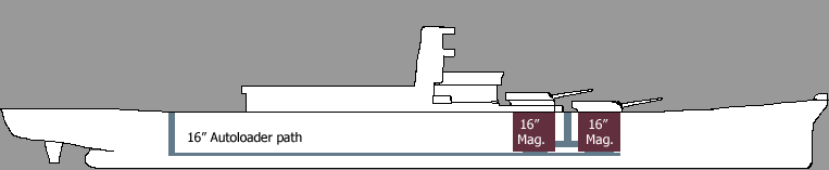
ASRS Specifications
| Capacity | Up to 48 by 48 inches (122 cm by 122 cm) navy pallets and JMIC containers weighing up to 3300 pounds (1497 kg) fully scalable. |
|---|---|
| Throughput | Up to 280 pallets per hour (70 pallets/hour per load station) |
| Inventory Management | Automatic load identification (RFID) linkable to Shipboard Warehouse Management System |
| Workload | Significant workload reductions through complete automation of storage and retrieval operations |
| Load Availability | 100% selective offload |
| Redundancy | Fully redundant storage and retrieval machine operation, complete manual backup capability. |
Hi-Rate VHT System
| Capabilities | Vertical, horizontal, diagonal travel; Full Loop System; Multiple platforms; Passage through ballistic/watertight boundaries; Automatic platform loading/unloading |
|---|---|
| Scalability | Pallet sized to weapons-elevator size (18 feet by 8 feet) |
| Capability | Up to 24000 pounds |
The ASRS and HVHT systems will also be used to manage modules located in the Multimission Bay.
Is it possible to expand the HVHT and ASRS across ships? So the UNREP process could be totally automatic: Iowa "emails" its supply requirements to supply ship, extends a boom to supply ship, which pulls the loaded containers automatically out of inventory and puts them on the transfer boom. This boom then moves the containers automatically to the correct storage locations.
The VHT system will have an opening at the stern of the ship near the former Turret 3. This 24000 pound capacity, 18 foot by 8 foot platform will drop down through the decks until it's even with "Broadway" and then is carried forward to the correct magazine. Having two of these VHT elevators operating at the same time will shorten the time required to reload. A second VHT elevator system will be placed between Turrets 1 and 2 to minimize the time required to reload the 16" cannon magazines. By using the VHT system at the rear of the ship additional ammunition can be delivered to the Iowa while it's in the process of firing on shore.
Containerized Ammunition Handling
The AGS uses a palletized ammunition system which holds 8 rounds in a single ammunition module. Cannon ammunition should be shipped in 20 foot containers. The containers have an "ammunition tray" in the bottom that holds the shells in place.
Crew Reduction/Optimized Manning
Use optimal manning design procedures. Get crew down as small as possible. Target crew size is 300. That's the crew of two DD(X) class destroyers, but much smaller than the 2400 the Iowa first sailed with (12.5% of the original crew size).
In addition to these enhancements, each 16" gun turret will receive an automatic loading system to totally automate the operations of each gun turret. Using the autoloader will reduce the crew size by 94 for each turret. The goal for the automatic loader will allow cannon to fire once every 15 seconds. Most of the components needed for an automatic loader are already in the turret. Need to automate:
- Shell handling from magazine to cannon breech
- Powder handling (bags are not suited to mechanization, use plastic/cardboard pizza boxes that snap together like Lego blocks to handle powder/propellant)
- Barrel cleaning and shell extraction (if cased/saboted rounds are used.)
- Shell inspection
- Barrel inspection
Damage Control
Use the Damage Control Tactical Management System (DCTMS). Use IBM SmartPath LED diagnostic system invented for computer hardware replacement to show which components need to be replaced. Damage control sensor systems shall have their own wireless network in addition to being tied into the main ship LAN systems.
Detection systems: Smoke detectors, carbon monoxide detectors, fire and flame detectors, a closed circuit television (CCTV) system, heat detectors, smart micro sensors, humidity monitors, and liquid level detectors. All these detectors should send data to the ship's control systems over the fiber optic LAN when possible, with wireless communications as a backup system. The data recorded by these systems can be seen using a web page, the ship's Integrated Condition Assessment System, or the ship's Damage Control Tactical Management System. In addition, all sensors shall be made "smart" by storing calibration information on a chip in the sensor and a server on the ship.
Combining the various internal sensor systems with the onboard fiber-optic LANs and wireless network will allow damage control teams to respond more efficiently, bringing the supplies needed to fix the damage detected by the ship. Progressive damage, or damage that has been repaired, will be updated automatically by the system and reported to the appropriate control systems (bridge, auxcon, damage control). The constant surveillance of the ship's internal sensors will also reduce or eliminate the time needed for investigators to search a compartment for damage.
Control stations will be located in critical areas of the ship like the Bridge, CIC, Damage Control Lockers, and Engineering Control Center. On-site responders will have access to wireless handheld devices that provide direction and information updates as needed.
Compartments below the main deck will be constantly monitored by liquid level detectors to monitor for flooding. The detectors will be placed at 2 and 6 inches above the compartment deck level, and at heights that correspond to flood levels of 10%, 25%, 50%, 75%, and 100%. This information will be fed automatically into the ship's automatic seakeeping software to calculate changes in ship's stability.
Each compartment will have at least two different types of smoke detector, a carbon monoxide detector, and a CCTV camera programmed to monitor film frames and compare them to typical activities. Ship's security will be able to use the CCTV system to gather evidence for security purposes and track the status of intruders.
Fire Suppression
A fire fighting system based on technologies from the Zumwalt-class destroyers and the San Antonio-class LPDs will be used on the Iowa. By combining the features of both of these ships, the Iowa benefits from the lessons learned in the construction and protection of these vessels. The use of these automated systems is critical for reducing manning and insuring ship survivability. The Iowa will use new technologies pioneered in the Zumwalt-class destroyers under the Autonomic Fire Suppression System (AFSS) program, such as smart valves, flexible hosing, nozzles, sensors, and autonomic operations to reduce the crew and time needed for damage control. In addition the use of cameras and thermal sensors to detect fires and automatically start the appropriate firefighting measure, usually a water mist system, to extinguish fires before they spread.
- Water Mist System - Two redundant systems (port and starboard) feed a centerline main that distributes an atomized mist of water to extinguish fires and protect the main and auxiliary machinery spaces. Water will also serve to control thermal transfer through metal of ship. Heat reduction occurs more than 1000 times faster than with traditional sprinklers and nozzles.
- HFP (Hepta Fluoro Propane) - Replaces HALON and provides protection for spaces that produce flammable vapors, as in aviation fuel (JP-5) space protection.
- AFFF System - Seven independent AFFF stations serve firefighting sprinkling systems and hose stations in the well deck, vehicle stowage areas, flight deck and all main and auxiliary machinery spaces, as well as from portable extinguishers.
- Seawater Sprinkling and Fire Stations - Provided from an offset loop firemain with 10 fire pumps distributed longitudinally in the machinery spaces. This ship is equipped with an extensive sprinkling arrangement - berthing, storerooms, magazines, and selected vital spaces - that provide protection for personnel and controls the spread of fire.
- Smoke Removal System - basically a custom system of pipes and fans to exhaust smoke from compartments aboard ship.
- Collective Protective System for living spaces
| Compartment | HFP | Carbon Dioxide | Water Mist | AFFF |
|---|---|---|---|---|
| AC | X | |||
| Berthing | X | |||
| Bridge | X | |||
| Auxiliary Control | X | |||
| CIC | X | |||
| Electrical | X | |||
| Flight Deck | X | |||
| Galley | X | X | ||
| Hangar | X | X | ||
| Machinery | X | X | ||
| Magazine | X | X | ||
| Multimission Bay | X | X | X | |
| Paint | X | |||
| Reactor | X | X | X |
Crew Equipment
Each crewmember will receive a small handheld computer. This "SailorPC" shall be based on the Nokia N800 Internet Tablet [SailorPC]. This handheld computer is approximately 3 inches by 5 inches in size, contains wireless networking capabilities, and runs a version of the Linux operating system. In addition to the obvious advantages of a small handheld computer (integrated personal information management, to do list, contact manager, email), this computer shall provide all the functions needed for a sailor to carry out their assignments. In addition, the wireless connectivity will allow the Sailor to access the Iowa's operations guide for any purpose. This will in turn allow the Sailor to refer to Navy guidelines, manuals, and checklists for any job aboard the Iowa.
The SailorPC shall also allow the Master Systems Displays located on the Bridge, CIC, AuxCon, and Engineering to identify the location of any sailor on the ship. This device will also allow direct point-to-point communications between any crewmember via the use of Voice Over IP (VoIP), instant messaging, or email. By using the N800's integrated camera, damage control parties and investigators can examine the scene of damage without having to be physically present. This camera also allows medical staff members to guide Sailors through more complex medical procedures. It may also be possible to attach various sensors directly to the SailorPC that can alert the user to dangerous conditions like low oxygen, chemical or biological attack, etc. This information shall also be submitted to the Iowa's command and control systems.
The uniforms provided to the Sailors and Marines of the Iowa shall include the integrated tourniquet technology created by Blackhawk. In addition to this first level of medical care, by changing the uniform shirts to include sensors that measure pulse, blood pressure, etc. and storing that data in the SailorPC the Iowa's medical staff will be able to provide better levels of health care. Combining this data with a longer-term medical history would allow Sailors and Marines to monitor the effectiveness of various health-related lifestyle changes and alert them to critical conditions (for example, a diabetic needing to take insulin). [UniformNotes]
Crew-centered ship features
Since the Iowa will be home to at least 300 people, and will be in service for at least 30 years, it only makes sense to apply the latest Ship Habitability standards and related best practices to the refitting. The Iowa shall feature full NBC overpressure protection as defined in NATO STANAG 4447, Nuclear, Biological, and Chemical Protection. The refitted Iowa shall also have provisions for female Sailors and Marines as an integral part of its construction. Individual efforts like those found in the San Antonio class landing craft, to include automated galley spaces, customized menus, and more efficient use of limited galley resources. In addition, the refit process will make extensive use of simulation to see if there is any benefit to using a centralized galley and Military Sealift Command-style food service.
The Iowa's sickbay will also be refitted to allow the medical crew to perform any necessary surgery and health care need. The Iowa will also serve as the testbed of the Sailor Health Monitoring System. The core of the Sailor Health Monitoring System shall be derived from the U.S. Army's Medical Communications for Combat Casualty Care (MC4) program. The project website (https://www.mc4.army.mil/index.asp) describes the benefits of the system as: "Medical Communications for Combat Casualty Care (MC4) integrates, fields and supports a medical information management system for Army tactical medical forces, enabling a comprehensive, lifelong electronic medical record for all Service members, and enhancing medical situational awareness for operational commanders." This system is also in use with the U.S. Air Force, and as of March 15, 2008, the system is tracking more than 4.5 million medical records.
Particular lessons learned from the San Antonio class ships:
- Consolidated Galleys - LPDs use a single, modern galley to feed officers in the wardroom; chief petty officers and senior non-commissioned officers in the CPO/SCNO mess; and embarked troops and ship's crew in the enlisted dining facility. Over 1200 Sailors and Marines can be well-fed three plus times per day.
- Food Service - LPDs will be able to provide traditional food service and pre-prepared food to meet the needs of Sailors and Marines. Its "combi" oven steams, dry roasts and combines both functions. The ovens can steam vegetables or broast any type of meat, even cook crispy French fries.
- Berth - sit up. LPDs will incorporate the sit-up berth for crew and embarked troops alike. For the first time personnel will have room to sit up in their bunks and to read or write on portable surfaces. Each berth will have individual ventilation and 40% more storage. The San Antonio Class features the sit-up berth to improve the quality of life at sea for Sailors and Marines. The redesigned berthing provides 40 percent more stowage space, room to sit upright in the rack, a reading/writing surface, pneumatic lift assist for opening and closing the rack, an electrical outlet, a mirror, a small shelf, a stowage area for boots and Marine battle helmets, and personal fan units. The berthing spaces are identical for any gender mix of Sailors and Marines and include adjacent sanitary facilities and lounges. Incorporates new crew comfort features including increased headroom, air-conditioning, and swivel-out laptop computer shelves.
- Berthing Spaces - Identical for embarked troops and ship's crew. In the LPDs, the berthing spaces will have similar sit-up berths, integral sanitary (head) facilities, and adjacent lounges. Chief petty officers and senior non-commissioned officers will live in modular six person bunkrooms with integrated sanitary facilities. Moreover, males and females will have equal facilities.
- Reverse Osmosis Water Generating Plant - Navy ships have traditionally used distillation for converting seawater into potable water, meaning the salt water was flashed and the condensate collected. LPDs will use a Reverse Osmosis system, also known as hyper filtration, which will remove particles as small as ions from the seawater through a semi-permeable membrane. It will purify water and remove salts and other impurities in order to obtain water for drinking, vehicle and aircraft wash downs and other shipboard uses. Equally important, this system will produce 72,000 gallons of potable water daily.
- Learning Resource Center/Electronic Classroom - Any organization is only as strong as its members. To that end, the Learning Resource Center and Electronic Classroom will receive a great deal of attention.
- Total Ship's Training System - Use MediaWiki to generate ship knowledge base. Require that all updates/changes be signed. One alternative to MediaWiki is JSPwiki, which runs as a Java program. This may fit in better with the Navy's Java-based systems.
- In addition to the information available from the Naval Personnel Development Command https://www.npdc.navy.mil/, this classroom will also include materials from the following free resources:
- MIT OpenCourseWare http://ocw.mit.edu/OcwWeb/web/home/home/index.htm
- University of California, Berkeley
- Webcasts of classes http://webcast.berkeley.edu/courses.php
- YouTube channel http://www.youtube.com/ucberkeley
- Carnegie-Mellon University Open Learning Initiative http://www.cmu.edu/oli/
- Tufts University OpenCourseWare http://ocw.tufts.edu/
- Stanford on iTunes http://itunes.stanford.edu/
- Utah State OpenCourseWare http://ocw.usu.edu/
- University of California, Irvine OpenCourseWare http://ocw.uci.edu/
- Johns Hopkins Bloomberg School of Public Health's OpenCourseWare http://ocw.jhsph.edu/
- University of Southern Queensland's OpenCourseWare http://ocw.usq.edu.au/
- The Open University http://openlearn.open.ac.uk/
- Free Online Education: Massive List of Resources http://education.jimmyr.com/
- Learn Out Loud (A/V classes, useful for foreign languages) http://www.learnoutloud.com/
- This classroom will also provide up-to-date and ship-installed versions of Java (SDK, Resource kits, Virtual Machines), Python (SciPy, SimPy, WxWindows, cryptographic functions, etc.), C++, C#, and C.
- Sailors have access to a copy of the OpenOffice.org office suite that is preloaded with templates for standard Navy reports, forms, and other documents.
- Versatile Exercise Mine System (VEMS) - VEMS is a leading mine countermeasures training and exercise evaluation system. VEMS is available in a number of configurations and able to emulate all types of mines. It will record a ships progress while the vessel attempts to locate, identify and neutralize the VEMS threat. VEMS is an excellent product for training MCM ships and crews producing feedback of performance results. VEMS is in service with the U.S. Navy, Royal Navy and a number of overseas forces worldwide.
Crew spaces can be repurposed quickly and efficiently using the modular storage options first outlined in [ModularStowagePaper]. Basically use the ISO 7166 Bulkhead Interface to create reconfigurable spaces. Also use "cornerless" design in compartments from the commercial shipbuilding industry to reduce maintenance requirements. Compartments will use photocells and motion sensors to automatically turn the lights on and off as needed. Most of the lighting above decks shall be based on the Advanced Lighting System currently under development for the Zumwalt class destroyer.
Created through the collaboration of RSL Fiber Systems with fellow Skyler subsidiary C3I, Inc of Hampton, NH; and developed through the guidance of Northrop Grumman Ship Systems and a number of U.S. Navy agencies, the ALS is a fully integrated system of lighting hardware and control equipment that can monitor and control fiber-optic based, LED, and conventional lighting throughout the ship, using the ship's existing communication network. RSL technology uses fiber optics to separate the light emission point from the power and light source by up to 200 meters/ 670 feet. Multiple locations can also be illuminated from a single source, and light escape, infared, and ultraviolet are drastically reduced – offering stealth, power, durability, and maintainability advantages over traditional lighting. [AlsNote]
Waste collection/Environmental considerations
All the crew's biological waste should be collected and held in Collection and Holding Tanks (CHT) like every other Navy ship. In the Iowa however, these CHT systems will serve as fuel sources for Microbial Fuel Cells developed by Penn State. These cells give off hydrogen and water as their waste, and clean the source water. The hydrogen created by these fuel cells shall be used as described earlier in Supplementary Power.
Supporting Systems
The refitted Iowa will continue the use of unmanned/automated systems to reduce crew size to the supporting systems used aboard the Iowa. Chief among these unmanned systems will be the Protector USV. This is a remotely-controlled, semi-autonomous 30 foot surface ship designed to expand force protection options for the surface commander. The system is already in extensive use with the navy of Singapore, and their employment of the system lead to these mission profiles:
- Use Protector USV as "submarine barrier patrol": equip Protectors with dipping sonars to try to detect submarines.
- Use Protector as a "barrier surface patrol" to deal with small boat threat.
- Use Protector USV will serve as a ready response for "man overboard" conditions in place of a lifeboat party.
The current Protector can operate for up to eight hours at a time. Though this time on station is excellent, it may be possible to extend it further through the use of a hybrid diesel-electric system. By converting the Protector to use electrically driven propulsion motors, and placing a "wireless power" receiver on the USV, the Iowa can beam power directly to the USV and increase its endurance. In calm seas or in port the Iowa could run a physical cable to the Protectors that are on duty. This engine combination would allow the Protector to save its diesel fuel for emergency situations when motive power is needed.
To provide additional support, several MQ-8B Sea Scout VTUAV's will be based on the Iowa. These helicopter UAV's will provide an organic air capability that would otherwise be missing. Specifically the Sea Scouts will have the following mission profiles:
- Antisubmarine warfare - Replace SH-60 Sea Hawk LAMPS helicopters in this role. If attached to a carrier battlegroup, the Sea Scouts will supplement the Sea Hawks and Ospreys rather than replacing them.
- Search and rescue - Augment or replace the existing aircraft.
- Observation for Naval Gunfire - The Fire Scout (Army version) was designed primarily to serve as a forward observer for artillery units. By bringing this capability to the Sea Scout, the Iowa gains an organic forward observer capability it would otherwise lack.
In addition, two Sea Scouts can carry the sensor for the AN/AES-1 mine detection system. As soon as Sea Scouts with stronger engines and greater cargo capacity are created, they will be equipped with the AES-1. This will provide the Iowa and her supporting vessels with an important mine-identification and elimination capability.
References
- http://cisd.dt.navy.mil/
- http://www.quietsolution.com/ <--Acoustic control coatings.
- http://www.navalengineers.com/
- http://www.boatdesign.net/
- http://ordnance.org/portal/
- ftp://www.foundation.csulb.edu/CCDoTT/Deliverables/
- http://www.ccdott.org/content/DS_fr.html
Books
Garzke, William H. Jr., and Robert O. Dulin, Jr, Battleships: United States Battleships, 1935-1992, 1995, Naval Institute Press, Annapolis. ISBN 15577501722. Only book to have comprehensive information on 1980's refits, and experimental shell designations. Nice line drawings as well, but they're a little small.
Sumrall, Robert F., IOWA Class Battleships: Their Design, Weapons & Equipment, 1988, Naval Institute Press, Annapolis. ISBN 0870212982. Contains some information on 1980's refits. Also contains color images and illustrations that are lacking in other sources.
Muir, Malcom, The IOWA Class Battleships, 1987, Sterling Publishing, New York. ISBN 0713717327. Has a great deal of information regarding the 16" guns, turret layouts, etc.
Friedman, Norman. U.S. Battleships: An Illustrated Design History, 1985, Naval Institute Press, Annapolis. ISBN 0870217151 <--Nice book. Very detailed information, but lacks information on 1980's refits.
Technology for the United States Navy and Marine Corps, 2000-2035 Becoming a 21st-Century Force: Volume 6: Platforms http://books.nap.edu/openbook.php?record_id=5839&page=14
Performance Parameters
GAO report number GAO-06-279R 'Issues Related to Navy Battleships'
Plans
U.S.S. Missouri website has PDF of builder's plans for Mighty Mo. http://www.ussmissouri.org/missouri.pdf I've used these plans to create my own line drawings of the Missouri, which is a sister ship to the Iowa. This should allow me to create a fairly accurate model.
http://hnsa.org/doc/index.html#bb Plans for the battleship New Jersey
Finding U.S. Navy Records and Drawings http://www.hnsa.org/doc/NARA/index.htm
Cannons
- http://www.navweaps.com/
- http://www.eugeneleeslover.com/GS-USN-PAGE.html
- http://www.eugeneleeslover.com/AMMUNITION/NAVORD-OP-769-TITLE-AND-FORWARD.html
- Millennium Gun info: http://www.gizmag.com/go/4006/
- RAM Accelerator: http://discovermagazine.com/1994/mar/rammingspeed349/article_print
- Electochemical Thermal XM Gun: http://www.dtic.mil/ndia/2006garm/tuesday/smith.pdf
- Modular Weapons Integration Lessons Learned: http://0-www.dtic.mil.mill1.sjlibrary.org/ndia/2006garm/tuesday/canaday.pdf
- Advanced Modular Gun: http://0-www.dtic.mil.mill1.sjlibrary.org/ndia/2006garm/tuesday/coladonato.pdf
- http://www.dtic.mil/ndia/ <--Guns, ammo, technology presentations.
Antitorpedo torpedo
STINET: http://stinet.dtic.mil/oai/oai?verb=getRecord&metadataPrefix=html&identifier=ADD017363 Anti-Torpedo Stern Defense System.
Antitorpedo torpedo Exhibit R-2 RDT&E Budget Item Justification, February 2006, 0603506N/Surface Ship Torpedo Defense.
Power Systems and Propulsion
GAO-06-789R Navy Propulsion Systems
- Navy Ship Propulsion Technologies: Options for Reducing Oil Use - Background for Congress http://handle.dtic.mil/100.2/ADA467382 CRS Report RL30622 Electric-Drive Propulsion for U.S. Navy Ships
- Integrated Power System (IPS) http://www.globalsecurity.org/military/systems/ship/systems/ips.htm
- Transformational Technology Core (TTC) http://www.globalsecurity.org/military/systems/ship/systems/ttc.htm
- Gas Turbine - Modular Helium Reactor http://gt-mhr.ga.com/
- Engineering Training http://www.fas.org/man/dod-101/navy/docs/swos/eng/index.html
Supplementary Power
Power generation options that do not rely on nuclear power.
Biological fuel cell information
- Fuel-Cell Microbes' Double Duty: Treat Water, Make Energy http://www.nsf.gov/news/news_summ.jsp?cntn_id=100337
- Waste Not, Want Not: Bacteria-driven cell produces hydrogen for fuel while cleaning wastewater http://www.nsf.gov/news/news_summ.jsp?cntn_id=104098
- Microbes Churn Out Hydrogen at Record Rate http://www.nsf.gov/news/news_summ.jsp?cntn_id=110648
- Clean, carbon-neutral hydrogen on the horizon http://live.psu.edu/story/27233
Tactical power systems
- Scientists develop portable generator that turns trash into electricity http://news.uns.purdue.edu/x/2007a/070201LadischBio.html
- Technology Review article http://www.technologyreview.com/Energy/18183/
- Skybuilt Power information about tactical power systems: http://www.skybuilt.com/pr_army.htm
- MISER information http://www.darpa.mil/dso/thrusts/physci/power/miser/index.htm
- DARPA Pursuing A Mobile Energy Recovery System For The Battlefield http://www.spacedaily.com/news/energy-tech-04zd.html
Power Distribution Systems
- Integrated Power System (IPS) http://www.globalsecurity.org/military/systems/ship/systems/ips.htm
- An Integrated Electric Power System: The Next Step by ADM Frank L. "Skip" Bowman, USN http://www.globalsecurity.org/military/library/report/2000/power_system.htm
- Integrated Fight Through Power Provides Electrical Redundancies http://findarticles.com/p/articles/mi_qa3738/is_200609/ai_n18622205
Control Systems
- Smart Ship Impact on LPD 17 Design Final Systems Engineering Report, November 30, 1997. http://www.fas.org/man/dod-101/sys/ship/docs/iismartship.html
- Navy Open Architecture Requirements Documents website http://www.nswc.navy.mil/wwwDL/B/OACE/ (This is the website with the information about what makes up the TOSA and related command functions.)
- See "Concepts and Application of Composable Forcenet" document: http://www.sparwar.navy.mil/sti/publications/pubs/index.html Document 20060926075. Discusses use of XHTML, XML, web mapping, peer-to-peer architecture.[4]
- Open Systems Joint Task Force homepage http://www.acq.osd.mil/osjtf/overview.html
- Open Source Software Institute-Navy Open Architecture Contract Guidebook http://www.oss-institute.org/index.php?option=com_content&task=view&id=184&Itemid=119
- Total Ship Computing Environment Infrastructure (TSCE-I) Hardware and Software Technology http://www.dtic.mil/dticasd/sbir/sbir043/sbir350.html
- Naval Open Architecture (ACC) https://acc.dau.mil/CommunityBrowser.aspx?id=18016〈=en-US
- NAVSEA Carderock Division Navy XML/SGML Repository http://www.dt.navy.mil/tot-shi-sys/des-int-pro/tec-inf-sys/xml-sgm-rep/index.html
- NAVSEA Carderock Division Interactive Electronic Technical Manuals http://www.dt.navy.mil/tot-shi-sys/des-int-pro/tec-inf-sys/etm/index.html
- NAVSEA Carderock Division CALS Standards http://www.dt.navy.mil/tot-shi-sys/des-int-pro/tec-inf-sys/cal-std/index.html
Crew Systems and Cost
- Navy Aircraft Carriers: Cost-Effectiveness of Conventionally and Nuclear-Powered Carriers, GAO/NSIAD-98-1, August 27, 1998.
- OPNAV Instruction 9640.1A "Shipboard Habitability Design Criteria Manual."
- Shipboard habitability website: http://www.habitability.net/ (Includes links to drawings to use for planning purposes.)
- Shipboard habitability machinery/outfitting catalog: https://90machinery.navsses.navy.mil/habitability/
- Documents from the DTIC site Scientific and Technical Information Network (STINET) Service (http://stinet.dtic.mil/) and Human Performace Center website (https://www.spider.hpc.navy.mil/)
Navy Documents and Studies
- Sea Power 21 http://www.nwdc.navy.mil/Concepts/Sea_Power_21/Sea_power_21.aspx
- Ship Operational Characteristics Study http://www.fas.org/man/dod-101/sys/ship/socs.htm
- Surface Combatant Force Requirement Study http://www.fas.org/man/dod-101/sys/ship/scfrs.htm
- Submarine of the Future http://www.fas.org/man/dod-101/sys/ship/docs/sotf.htm
- Surface Combatant 21 http://www.fas.org/man/dod-101/sys/ship/sc-21.htm
- Surface Officer Warfare School http://www.fas.org/man/dod-101/navy/docs/swos/index.html
Research Papers and Sites
- http://www.dtic.mil/doctrine/ Research papers.
- Naval Postgraduate School Total Ship Systems Engineering website http://www.nps.edu/academics/gseas/tsse/
- Center for Innovation in Ship Design http://cisd.dt.navy.mil/
- NAVSEA Carderock Computer Modeling and Simulation http://ocean.dt.navy.mil/
- http://www.usna.edu/NAOE/courses/en200/ Course materials related to Naval Architecture and Engineering.
Ship Sites
Inspiration from other ships in the U.S. Navy and foreign navies.
San Antonio
- LPD-17 San Antonio class: https://www.pms317.navy.mil/tech/tech.asp
- Defense Industry Daily Coverage http://www.defenseindustrydaily.com/lpd17-san-antonio-class-the-usas-new-amphibious-ships-updated-02322/
- Naval Technology site: http://www.naval-technology.com/projects/lpd17/
- Global Security article: http://www.globalsecurity.org/military/systems/ship/lpd-17.htm
Zumwalt/DD(X)/DDG-1000 Destroyer
Global Security
- http://www.globalsecurity.org/military/systems/ship/dd-21.htm
- http://www.globalsecurity.org/military/systems/ship/dd-x.htm
Other references
- Defense Industry Daily: http://www.defenseindustrydaily.com/dead-aim-or-dead-end-the-usas-ddg1000-zumwalt-class-program-02574/
- Wikipedia: http://en.wikipedia.org/wiki/Zumwalt_class_destroyer
- Naval Technology site: http://www.naval-technology.com/projects/dd21/
- CRS Report RL32109 Navy DDG-1000 (DD(X)) and CG(X) Ship Acquisition Programs
CVN-21/CVN-77 George H.W. Bush
- Defense Industry Daily coverage: http://www.defenseindustrydaily.com/design-preparations-continue-for-the-usas-new-cvn21-supercarrier-01494/
- Global Security article: http://www.globalsecurity.org/military/systems/ship/cvx.htm
Sea Fighter/X-Craft
- Wikipedia: http://en.wikipedia.org/wiki/Sea_Fighter
- Global Security article: http://www.globalsecurity.org/military/systems/ship/x-craft.htm
Littoral Combat Ship
- Naval Technology site: http://www.naval-technology.com/projects/littoral/
- Global Security article: http://www.globalsecurity.org/military/systems/ship/lcs.htm
Virginia-class submarines
- Wikipedia: http://en.wikipedia.org/wiki/Virginia_class_submarine
- Global Security article: http://www.globalsecurity.org/military/systems/ship/ssn-774.htm
- http://www.fas.org/man/dod-101/sys/ship/docs/990100-nssn.htm
- http://www.harpoondatabases.com/Encyclopedia/Entry1383.aspx <-- Virginia class submarine info.
STANFLEX 300 Ships
- FROM: Jane's IDR August 04: Flex fleet: Denmark's new standard warships emerge (Word Document): http://forum.keypublishing.co.uk/attachment.php?attachmentid=45846
- Naval Technology article: http://www.naval-technology.com/projects/fly/
Experimental/Technology Demonstrator craft
- Joint High Speed Vessel (Joint HSV): http://www.globalsecurity.org/military/library/report/2002/ConceptHSV.htm
- Stilleto: http://www.globalsecurity.org/military/systems/ship/stiletto.htm Particularly interested in the command/planning systems, on-board LAN. See following paragraph:
"In addition to the unique hull design and all carbon fiber construction, Stiletto also employs an 'electronic keel' that combines the processing power of a bank of supercomputers with the networking capability coupled to a robust onboard communications system that facilitates data-sharing with other nodes on internal and external networks. For the SEALS, this means mission planning can continue as the assault team approaches the target insertion point. Outfitting of equipment is extremely flexible with a 'plug and play' data bus that uses internet protocol as its standard. Equipment installation is as simple as securing it into a universal electronic rack located in onboard manned mission planning modules and the network connections are made through simple USB port plug-ins."
Manufacturer Sites
General Dynamics
- General Dynamics Ordnance and Tactical Systems: http://www.gd-ots.com/
- GD Littoral Combat Ship: http://www.gdlcs.com/
- GD Armament and Technical Products: http://www.gdatp.com/
- Hi-Rate VHT System information: http://www.gdatp.com/Products/PDFs/VHT%20System.pdf
- Auto Storage and Retrieval System information: http://www.gdatp.com/products/PDFs/ASRS.pdf
Unsorted
- http://www.nps.edu/Research/newsletters/Jun01ResNews.pdf
- U.S. Military Laser briefing site: http://radhealth.usuhs.mil/
- http://www.globalsecurity.org/military/library/budget/fy2003/fy03_DOTE_Annual_Report.pdf
- https://teamware.dt.navy.mil/seatech.nsf
Footnotes
[1]Statement of the Honorable John J. Young, Jr., Assistant Secretary of the Navy (Research, Development and Acquisition) and RADM Charles S. Hamilton, II Program Executive Officer For Ships, before the Projection Forces Subcommittee of the House Armed Services Committee on DD(X) Shipbuilding Program July 19, 2005. DDX_19Jul05_statement.doc
[2]GAO-05-752R Progress of the DD(X) Destroyer Program, Progress of DDX Report d05752r.pdf
[4]Related references for automation:
- M.G. Ceruti and B.J. Powers, "Intelligent Agents for ForceNet: Greater Dependability in Network-Centric Warfare", Supplemental Volume of the Proc. of the IEEE International Conference on Dependable Systems and Networks (DSN 2004), pp. 46-47, June 2004.
- R.W. Mayo, VADM, USN and J. Nathman, VADM, USN, "Sea Power 21 Series - Part V: ForceNet: Turning Information into Power," Naval Institute Proceedings, vol. 129, no. 2, pp 42-46, Feb. 2003.
- J.D. Neushul and M.G. Ceruti, "Sensor Data Access and Integration Using XML Schemas for FORCEnet", Space and Naval Warfare Systems Center San Diego Biennial Review, 2005.
- V. Clark, ADM, USN, "Sea Power 21 Series - Part I: Projecting Decisive Joint Capabilities," Naval Institute Proceedings, vol. 128, no. 10, pp 32-41, Feb. 2003.
[SubmarineSteel] http://www.globalsecurity.org/military/systems/ship/deep.htm A submarine's hull is normally constructed of steel, or exceptionally of titanium. Special High Yield (HY) steel alloys have been developed to increase the diving depth of submarines, although the improved depth performance of these alloys imposes a price of increased fabrication challenges. These special steels are denominated by their yield stress in thousands of pounds per square inch -- thus HY-80 steel has a yield stress of 80,000 pounds per square inch (corresponding to a depth of 1,800 feet), HY-100 a a yield stress of 100,000 pounds per square inch (corresponding to a depth of 2,250 feet), and so on.
http://en.wikipedia.org/wiki/Ship-Submarine_Recycling_Program contains information about the Ship-Submarine Recycling Program, including a list of ships and submarines waiting to be demilitarized and scrapped. There are at least 25 Los Angeles-class attack subs, which use HY-100 steel for their hulls, waiting to be recycled.
[SmartGlass] Information available from http://en.wikipedia.org/wiki/Smart_glass and http://www.electronicglasswall.com/
[EDP] http://www.research.ibm.com/ed/ The Everywhere Displays project aims to develop systems that allow the transformation of every surface in a space into a projected "touch screen".
[APfHSS] See Interim Progress Report on the Economic Analysis of Alternative Powering Concepts for High Speed Sealift Ships document, available at ftp://ccdoft.org/Deliverables/2000/task2.9/task2.9.pdf
[ContainerDimensions] from http://en.wikipedia.org/wiki/Shipping_containers#Standard_containers
| 20′ container | 40′ container | 45′ high-cube container | |||||
|---|---|---|---|---|---|---|---|
| imperial | metric | imperial | metric | imperial | metric | ||
| external dimensions | length | 19' 10 1/2" | 6.058 m | 40′ 0″ | 12.192 m | 45′ 0″ | 13.716 m |
| width | 8′ 0″ | 2.438 m | 8′ 0″ | 2.438 m | 8′ 0″ | 2.438 m | |
| height | 8′ 6″ | 2.591 m | 8′ 6″ | 2.591 m | 9′ 6″ | 2.896 m | |
| interior dimensions | length | 18′ 10 5⁄16″ | 5.758 m | 39′ 5 45⁄64″ | 12.032 m | 44′ 4″ | 13.556 m |
| width | 7′ 8 19⁄32″ | 2.352 m | 7′ 8 19⁄32″ | 2.352 m | 7′ 8 19⁄32″ | 2.352 m | |
| height | 7′ 9 57⁄64″ | 2.385 m | 7′ 9 57⁄64″ | 2.385 m | 8′ 9 15⁄16″ | 2.698 m | |
| door aperture | width | 7′ 8 ⅛″ | 2.343 m | 7′ 8 ⅛″ | 2.343 m | 7′ 8 ⅛″ | 2.343 m |
| height | 7′ 5 ¾″ | 2.280 m | 7′ 5 ¾″ | 2.280 m | 8′ 5 49⁄64″ | 2.585 m | |
| volume | 1,169 ft³ | 33.1 m³ | 2,385 ft³ | 67.5 m³ | 3,040 ft³ | 86.1 m³ | |
| maximum gross mass | 52,910 lb | 24,000 kg | 67,200 lb | 30,480 kg | 67,200 lb | 30,480 kg | |
| empty weight | 4,850 lb | 2,200 kg | 8,380 lb | 3,800 kg | 10,580 lb | 4,800 kg | |
| net load | 48,060 lb | 21,800 kg | 58,820 lb | 26,680 kg | 56,620 lb | 25,680 kg | |
20' heavy tested containers are available for heavy goods (e.g. heavy machinery). These allow a maximum weight of 67,200 lb (30,480 kg), an empty weight of 5,290 lb (2,400 kg) and a net load of 61,910 lb (28,080 kg).
[MissionContainerTypes] Due to the standardized nature of the container size, creating mission-specific modules is possible. This allows a ship that was formerly limited to one role to be re-equipped and relaunched to perform additional mission types. Module replacement should take no more than 12 hours, and the target time is 6 hours. Mission modules already in use by the Danish Navy on their STANFLEX 300 vessels include modules for:
- Disaster relief
- Hospital ship
- Mine laying and mine clearing
- Facility evacuation (civilian transport)
- Embargo operations
- Amphibious operations
- SIGINT (signals intelligence) gathering
There are also several weapon-carrying modules that exist now, and several more can be created, as shown in the following list:
- Mk 56 SAM launchers holding 12 RIM-162 ESSMs
- Harpoon II launcher holding 8 missiles
- AGS carrier
[ModulePayloads] Potential payloads and configurations for side-mounted modules.
- Torpedo launchers
- VLS systems
- Cannon systems ranging from Advanced Gun Systems to 25mm chain guns
- CIWS/RAM launchers
- Decoy launchers
- Antitorpedo torpedo launchers
- Side scan sonar, radar, and other sensor packages
- Ammunition magazines
- Drone systems (Protector USV)
- SEAL/Special Forces delivery options
- Fuel storage (for ships or aircraft)
- Cargo pods
- Medical systems
- Small boat defense (25mm cannon, 40mm grenade launchers [SUWMissionPackage])
- Active Denial Systems/Silent Guardian developed by Raytheon
- Troop transportation
[rrwj] More information about waterjets in general and Rolls-Royce waterjets in particular:
- Article about Waterjet Propulsion at The Marine Encyclopedia http://navgathi.info/index.php/Waterjet_propulsion
- Hamilton Jet - Produce waterjets with power output of 150 to 3000 kW (Small boats) http://www.hamiltonjet.co.nz/
- Rolls-Royce Marine Waterjets - Produce waterjets with power output ranging from 50kW to above 36MW. http://www.rolls-royce.com/marine/products/propulsion/waterjets/default.jsp
- Article: "Why New Warships will be powered by Waterjets" http://www.marinelink.com/Story/ShowStory.aspx?StoryID=206051
- New compact, high-performance waterjets from Wartsila - http://www.webwire.com/ViewPressRel_print.asp?aId=16098
[PropShaftInfo] Prop Shaft Information (including propulsion engines)
| Propshaft | Length | Avg Thickness | Volume (cubic feet) |
|---|---|---|---|
| 1 | 105.26 feet | 18.25 inches | 764.85 |
| 2 | 49.416 feet | 18.25 inches | 359.07 |
| 3 | 7.3 feet | 18.25 inches | 53.04 |
| 4 | 72.73 feet | 18.25 inches | 528.48 |
| Total | 1705.44 |
1 cubic foot of steel weighs 490 lbs. So removing the 1705.44 cubic feet of unnecessary propshaft will save 835665.6 pounds or 417.83 tons.
[AnechoicTiles] http://www.harpoondatabases.com/Encyclopedia/Entry1383.aspx "The sub is coated in anechoic coating and the Virginias are said to be as quiet as the Russian Akula class."
[SOTF] Submarine of the Future document, available from http://www.fas.org/man/dod-101/sys/ship/docs/sotf.htm
[SUWMissionPackage] http://www.news.navy.mil/search/print.asp?story_id=31482 "SUW Mission Package Attacks Small Boat Threat for LCS." Story number NNS070925-24 These components include:
- electro-optical/infrared sensors mounted on a vertical take off unmanned air vehicle to provide over-the-horizon detection;
- 30mm guns to kill close-in targets;
- four non-line-of-sight launching system (NLOS-LS) container launch units or "missile-in-a-box" systems, with each system containing 15 offensive missiles;
- and the MH-60R armed helicopter for surveillance and attack missions.
[TPS] Scientists develop portable generator that turns trash into electricity http://news.uns.purdue.edu/x/2007a/070201LadischBio.html
[PennStateFuelCells] Articles about Penn State microbial fuel cells:
- Microbes Churn Out Hydrogen at Record Rate http://www.nsf.gov/news/news_summ.jsp?cntn_id=110648 and http://www.psu.edu/ur/2007/biohydrogen.htm
- Fuel-Cell Microbes' Double Duty: Treat Water, Make Energy http://www.nsf.gov/news/news_summ.jsp?cntn_id=100337
- Waste Not, Want Not: Bacteria-driven cell produces hydrogen for fuel while cleaning wastewater http://www.nsf.gov/news/news_summ.jsp?cntn_id=104098
[SixTeenInchPropellantReferences]
- 155 mm Uniflex Modular Charge System http://proceedings.ndia.org/5550/tues_and_wed_briefings/sjoberg1.pdf
- UNIFLEX 2 IM Modular Charge System http://www.baesystems.com/ProductsServices/l_and_a_bof_uniflex.html
- "...including a fully flexible modular charge magazine to replace the limited 18-rack pre-loaded magazine. The new system is to use Uniflex 2 IM modular charges, and will enable operators to flexibly choose between 12 increments for each shot from a central charge magazine of over 100 charges and half-charges, rather than the limited pre-loaded system." Australian Defense Business Review, Volume 25, Number 10, 30 November 2006. Page 8, describing new artillery system procurement.
[Uniflex2ModularCharge] http://www.baesystems.com/ProductsServices/l_and_a_bof_uniflex.html The UNIFLEX 2IM modular charge system consist of two size of combustible charge cases; one full size and one half size case. Both are filled with the same type of Insensitive GUDN propellant.
When using UNIFLEX 2IM in an L52 system, no less than 12 different increments are available, which significantly increases an autonomous gun system's Multiple Rounds Simultaneous Impact (MRSI) capability and gives a very good range overlapping between the increments.
The UNIFLEX 2IM modular charge system is easy to handle, compared with conventional bag charge systems, instead of removing bags, modules are put together to attain the correct velocity. Thus there will be no useless remaining charge bags when using UNIFLEX 2IM, eliminating another logistic problem.
[VlrmAB] http://www.atk.com/customer_solutions_missionsystems/cs_ms_w_hs_vlrm-ab.asp
- Denel Products & Capabilities http://www.denel.co.za/Landsystems/LS_ArtillerySysVLAP.pdf
- New Indirect Fire Capabilities from Industry Cooperation 2004-06-16 http://www.dtic.mil/ndia/2004armaments/DayII/SessionII/13Fitchat_South_African_COOP.pdf
- Howitzer 2000 Tank Lobs V-LAP Projectile Nearly 60 Kilometers http://www.spacedaily.com/reports/Howitzer_2000_Tank_Lobs_V_LAP_Projectile_Nearly_60_Kilometers.html
[FutureCannon] ElectroThermal Chemical Guns - BAE Systems "Lightning Bolt" 120mm ETC gun test vehicle
- http://www.emlsymposium.org/13th_papers/docs/A-EML086.pdf
- http://www.spacedaily.com/news/milspace-04y.html
Combustion Light Gas Guns - Utron Inc. is the only player in this area as of 2008.
- http://en.wikipedia.org/wiki/Combustion_light_gas_gun
- http://www.statejournal.com/story.cfm?func=viewstory&storyid=20077&catid=165&printview=1
[AvlsInfo] Official name for the Peripheral Vertical Launch System is the MK57 Vertical Launching System. It's only scheduled for the Zumwalt-class destroyer at this time (2007), but it's likely it will be included on future surface combat ships.
MK 57 VLS Physical Dimensions (4-cell Module)
| Height: | 26 feet |
|---|---|
| Length: | 14.2 feet (14 feet, 2.6 inches) |
| Width: | 7.25 feet (7 feet, 3 inches) |
| Weight: | 33,600 lbs |
| Canister Width: | 28 inches |
| Canister Length: | 283 inches (23 feet, 7 inches) |
| Max. Encanistered Weight: | 9,020 lbs |
"The MK 57 VLS is designed not only to support existing VLS encanistered missiles but also provides for growth in missile volume and weight."
"The MK 57 VLS is designed to accommodate both current and future missile technologies without major launcher modifications. It is flexible enough to handle lighter missiles, such as the Evolved Seasparrow, as well as the larger, heavier missiles required for ballistic missile defense."
"The robust MK 57 VLS gas management system can accommodate new missile designs having up to 45% greater rocket motor mass flow rate than current-generation rocket motors. The unique symmetric geometry of the U-shaped gas management system facilitates the egress of gases, while minimizing flow into witness cells and reversed flow into the active cell. Elimination of a missile deluge system significantly reduces maintenance and personnel requirements, and protects against accidental missile wet-down." Above information is from Raytheon's website.
[SensorFuzedWeapon] BLU-108/B specifications
- Length: 78.8 cm (31.0 in)
- Diameter: 13.3 cm (5.25 in)
- Maximum lateral dimension: 18.4 cm (7.25 in)
- Weight: 29.5 kg (65 lb)
Skeet specifications
- Height: 9.5 cm (3.75 in).
- Diameter: 12.7 cm (5.0 in).
- Weight: 3.4 kg (7.5 lb).
- Seeker: Dual-mode active (laser) and passive (infrared) sensors.
- Explosive: 945 g (2.08 lb) Octol.
- Kill mechanism: Explosively formed penetrator and fragmentation.
[RhinoLining] http://www.rhinolinings.com/about.php?id=4&news_id=11
[SeaTentacle] http://www.nps.edu/academics/gseas/tsse/subPages/2005Project.html (includes source documents) Executive Summary The Navy is currently undergoing a transformation with a focus centered on littoral warfare. In order to successfully operate in the littorals, a mastery of the littoral Anti-Submarine Warfare (ASW) situation is required. One approach deals with the deployment of large Unmanned Underwater Vehicles (UUV's) to establish a littoral ASW sensor grid. The ship designed for the carrying, deployment, and maintenance of these UUV's is the catamaran SEA TENTACLE. SEA TENTACLE is a high-speed catamaran that is capable of conducting operations in shallow water. It is designed to either act independently or in conjunction with other naval forces. The design is focused around the capability to carry, deploy, and maintain large numbers of UUV's. In addition the ship's combat system provides for robust offensive and defensive capabilities in the realm of ASW, Surface Warfare, and Anti-Air-Warfare.
[JointAccess] http://www.nps.edu/academics/gseas/tsse/subPages/2004Project_2.html (includes source documents)
Executive Summary The current notion of seabasing requires that three Battalion Landing Teams (BLT) of a 2025 Joint Expeditionary Brigade (JEB) need to be able to transit from the Sea Base to the objective within a 10 hour period. Of the three BLTs, two of them must be transported by surface craft a distance of no more than 200nm in sea state 4 or less. The two surface bound BLTs need to be loaded onto the transporting craft and delivered to shore, whether it is a port facility or austere beachhead. There is no current or future system of connectors to meet all the time-distance, sea state, and interface flexibility requirements for this aspect of seabasing. To meet these requirements a High Speed Assault Connector (HSAC) is needed which either augments current or replaces existing connector platforms to deliver and support the required forces ashore. The Joint ACCESS is a HSAC that brings the necessary speed, payload capacity, interface capability, and mission flexibility needed to fill the Sea Base to shore transportation gap. With a maximum speed of 43kts and payload capacity of 800LT, 12 Joint ACCESS trimaran can transit 200nm and fully offload in 7 hours. Its beachable design uses a floating bow ramp to reach out to austere beaches, while its combat system suite provides self defense in addition to robust offensive capabilities.
[ModularStowagePaper] http://www.navalengineers.org/Publications/Proceedings/ADAY2004Abstracts.html
Modular Stowage Is Here for The Transformed Fleet by Pat Lane and Ted Williams
The Naval Surface Warfare Center Carderock Division has developed an open architecture, bulkhead-mounted, stowage system that is fully modular, and reconfigurable without the use of tools. A store room can be totally reconfigured or even converted into an office, a library or other desired space in a matter of less than an hour, using off-the-shelf components. This inherent flexibility allows for fully responsive, safe, efficient stowage to meet rapidly changing mission requirements of today's and future ships.
The backbone of the system is vertically-mounted ISO 7166 slot-and-hole track, similar to that used on airliners to mount seats to the floor. Various fixtures fitted with integral mounting locks, have been produced to fit the track, including shelves and brackets of varying sizes, padeyes, hooks, desktops and book cases. The major components have been shock qualified for use on combatants. More items, including hose racks, lockers and junction boxes are being developed. Packup Kit containers could be designed to lock directly onto the tracks rather than requiring shelves as they now do.
[SELinux] http://www.nsa.gov/selinux/
[DragonFire2] Marine Corps Warfighting Laboratory Dragon Fire II Experimental System NDIA Briefing - http://www.dtic.mil/ndia/2004armaments/DayII/SessionII/07Lindsey_Dragon_Fire_II.pdf
[SotSAnt] http://www.military-information-technology.com/article.cfm?DocID=759 [OppAnt] http://stinet.dtic.mil/oai/oai?verb=getRecord&metadataPrefix=html&identifier=ADA443324
"An opportunistic array is an integrated ship-wide digital phased-array radar, where antenna elements are placed at available open areas over the entire ship's length. Such an array has the potential to fulfill many of the Navy's missions, including ballistic missile defence (BMD) where the radar mission encompasses exoatmospheric surveillance, tracking and preliminary discrimination. Advantages of opportunistic arrays include:
- Enhanced stealth - since low-profile antennas reduce the ship's RCS;
- High angular resolution - as the entire ship's length forms the "aperture" and produces a narrow beamwidth;
- Potentially lower costs - through the use of COTS technology and a flexible digital antenna architecture that reduces the number of distinct radar systems required."
http://www.nps.edu/Research/Meyer/PDF/Meyer%20Institute%20Logbook%20Volume%203.pdf
- 21.3" Ruggedized Flat-Panel Display http://www.baesystems.com/ProductsServices/bae_prod_eis_rfm213.html
- 20.1" Ruggedized Flat-Panel Display http://www.baesystems.com/ProductsServices/bae_prod_eis_rfm201.html
- Q-70 series display information
[DamageControlTacticalMgmtSystem] From http://www.dcfp.navy.mil/software/dctms.htm
The Damage Control Tactical Management System was designed to be both a tactical management tool for damage control and personnel casualties, personnel management, equipment assets and as a training tool to assist in the administration management for damage control and medical drills.
DCTMS is a very powerful tool for command and control and the damage control and medical warfare areas. The systems design has incorporated all of the features required to:
- Plot and track damage control and medical casualties electronically
- Improve communications
- Maintain damage control libraries
- Track equipment assets
- Track contractor work locations
- Maintain drill guide libraries
DCTMS is comprised of three modules and numerous databases that tie this powerful system together. The database is complex and contains an enormous library of damage control information that assists the user in virtually any task. While the following list is not all inclusive it gives you some idea of the power of DCTMS and how it can be used. It provides a wealth of information for improving situational awareness.
- Damage Control Checklists; A populated checklist that is actuated when a casualty is plotted. Automatically brings all the required procedures to combat the particular casualty.
- Damage Control Doctrines; Ships specific required doctrines database.
- Casualty Plotting; Populated casualty ICONs toolbar covering all possibly casualty types. Automatically replicated on all work station in the work group eliminating the need for each station to plot the same casualty. Eliminates the possibility of missed communications and in-accurate casualty plots. A clear graphical display.
- Gas Free: Allows you to track contractor work showing locations of all hot work and gas free operations. Provides potential locations were a greater chance of a mishap may occur, especially during availabilities.
- Equipment Assets; Graphical display of the locations of all damage control equipment. Filters to find specific equipment. Aids maintenance personnel in equipment locations for maintenance and inventories.
- CCOL's; Links into the ships electronic CCOL Database.
- Kill Cards; A database that contains complete boundaries for fire, smoke or flooding and isolation of the various systems in any shipboard space.
- Electronic Library; while this is not actually part of DCTMS it is loaded onto the laptop at installation to provide the most comprehensive Damage Control library available. Soon to be added will a variety of CBT videos to enhance shipboard training and to relieve shipboard personnel from the duties of having to train individual sailors in many PQS items.
- Internet Access; Available to the system intended for access into the NAVSEA DC/FP or NKO website for training, equipment and maintenance issues and updates to the damage control information highway.
- Drill guide development; provide a simplistic tool to develop a standard drill guide by using drop down menus and information databases. Builds a library of casualties and damage control drill guides for future training requirements. Eliminates numerous hours in drill development and provides the standard drill guide format for the fleet.
- DC Plates; Provides access to the ships complete electronic copy of Damage Control Plates.
- FM/CHW Diagrams; Provides mimic of both the FM and CHW showing system status and equipment components.
- Damage Modeling; Models damage control casualties, showing expected damage based on damage input and crew response.
DCTMS aids in situational awareness and allows command and control to see the big picture to assist them in making quick critical decisions in a casualty crisis.
- Graphically displays the locations of all casualties on the ships deck plan.
- Graphically displays the locations of all personnel casualties on the ships deck plan.
- Graphically displays the location of all repair teams on the ships deck plan.
- Graphically displays the location of all medical response teams on the ships deck plan.
Information dialog boxes associated with each casualty can be accessed by all levels of command and control at anytime to ascertain the status of the particular casualty without verbal communications to Damage Control Central or DCRS stations. This allows command and control to have complete real time status of any casualty at anytime without interrupting the damage control organization combating the casualty.
[SailorPC] Nokia N800 Page (Flash based) http://www.nseries.com/products/n800/#l=products,n800
[UniformNotes] http://www.gizmag.com/go/7974/ Integrated tourniquet clothing system aims to save lives on the battlefield
September 7, 2007 One of the most common causes of preventable deaths in tactical environment is bleeding to death, so any advance in providing assistance as quickly as possible in such situations clearly has the potential to save lives. This is the thinking behind a new range of clothing from Blackhawk that integrates tourniquets into the design which can be immediately accessed by the wearer, their buddy, or a medic to minimize the loss of blood.
The Integrated Tourniquet System (I.T.S) has been introduced into the new "Warrior Wear" apparel line and consists of four tourniquets in the pants and four tourniquets in the shirt (two in the short sleeve version) which are correctly positioned and oriented to the upper and lower extremities. The clothing can be worn under existing gear and users can train with the system without having to replace each tourniquet after a single use, which enables users to use the same system they will wear in tactical operations.
The System was the brainchild of Dr. Keith Rose. Dr. Rose, a tactical medicine consultant for Blackhawk's Special Operations Division with several years military experience on a forward surgical team and extensive field experience in trauma and burns.
"The majority of preventable deaths come from loss of blood resulting from leg and arm wounds that is not protected by body armor. Ten percent of preventable combat deaths are from extremity bleeding and 50-70% of all combat injuries are extremity wounds," explained Dr. Rose.
Blackhawk intends to incorporate I.T.S. into its current line of apparel and will also license the technology to other manufactures that currently provide apparel to the Military, Law Enforcement, and Outdoor community.
The I.T.S. system is in the final phases of testing and should be available during the first quarter of 2008.
http://en.wikipedia.org/wiki/Smart_Shirt
The Smart Shirt is manufactured by Sensatex, but was developed by the Georgia Institute of Technology and originally funded by the US military's 21st Century Land Warrior Program and the Defense Advance Research Projects Agency (Bowie 2000). The shirt contains sensors that can be used to monitor vital signs such as heart rate, EKG, respiration, and blood pressure (Tollen 2001).
The design of the Interconnection Technology allows for a fully-fashioned garment to be produced from two-dimensional fabric without the need to cut and sew the garment which allows for it to “be incorporated into any fabric (cotton, lycra, wool, silk, etc.) or blend of fabrics without effecting the look, feel or integrity of the fabric that it is replacing”(Sensatex 2005). The information collected by the shirt can be accessed from a remote location therefore improving diagnosis time and also providing a sense of security for the user.
[AlsInfo] http://www.defenseindustrydaily.com/ddg1000-destroyers-to-get-als-lighting-system-02977
Glossary
| ABL | Armored Box Launcher | Now obsolete horizontal launch systems used on the Iowa class battleships during their 1980's service. Held four BGM-109 Tomahawk cruise missiles. |
| AEPA | Advanced Electronic Phased Array | Synonym for Active Electronically Scanned Array, defined below. |
| AESA | Active Electronically Scanned Array | Pronounced A-ESA. An Active Electronically Scanned Array (AESA), also known as active phased array radar is a type of radar whose transmitter and receiver functions are composed of numerous small transmit/receive (T/R) modules. AESA radars feature short to instantaneous (millisecond) scanning rates and have a desirable low probability of intercept. Reference: http://en.wikipedia.org/wiki/Active_Electronically_Scanned_Array |
| AFFF | Aqueous Film Forming Foam | A firefighting system that works by spraying a foam on top of burning fuel, reducing temperature and choking off the fire's oxygen supply. |
| AFSS | Autonomic Fire Suppression System | Automatically activated shipborne firefighting system developed for the Zumwalt-class destroyers. |
| AGS | Advanced Gun System | 155mm main cannon armament under development for the Zumwalt-class destroyers. |
| ALS | Advanced Lighting System | A fiber optic based lighting system developed for the U.S. Navy. Uses fiber optics and a "light pump" (a large bulb) to provide illumination around a ship. |
| AMOS | Advanced Mortar System | A Swedish weapon, the AMOS consists of twin 120mm breech loading mortar tubes capable of launching a round every seven seconds. Serves as the basis for automated decoy launch systems. |
| AMRFS | Advanced Multifunction RF System | A multifunction system that takes the place of several takes the place of several existing radar and communications systems by consolidating multiple antennas into one multifunction array. |
| ATT | Antitorpedo torpedo | As the name implies, a small self guided underwater munition designed to intercept and destroy incoming torpedoes before they can threaten a ship. Based on the Compact Rapid Attack Weapon. |
| AuxCon | Auxiliary Control | Secondary control center that allows the ship to continue to fight effectively in the event the bridge is destroyed. |
| CAVE | Conformal Acoustic Velocity Sensor | Sonar system developed for the Virginia-class submarines that replaces the traditional hydrophones with fiber optic based hydrophones arranged in an array of elements. These arrays can be shaped to the radius of a ship's hull, hence conformal. |
| CCOL | Compartment Check Off List | Checklist designed for crew members to follow in the event of a damage control situation. |
| CEC | Combat Engagement Center | Compartment that holds all the command systems for combat systems in the ship. This is a duplicate of the Combat Information Center, which is unique to the Iowa-class vessels. |
| CEC | Cooperative Engagement Capability | A system under development for the U.S. Navy designed to allow all the ships and aircraft to share data for tactical purposes. For example, it will allow surface ships to use sonar targeting data from submarines to attack enemy subs. |
| CIC | Combat Information Center | Compartment that holds all the command systems for combat systems in the ship. |
| COTS | Commercial Off the Shelf | Equipment purchased by the military directly from a commercial vendor instead of using a proprietary or militarized version. Most frequently used in conjunction with hardware and software, though becoming more prevalent with construction materials. |
| CRAW | Compact Rapid Attack Weapon | A weapon under development for the Navy, it's basically a "pocket torpedo" that can be carried by vertical take off unmanned aerial vehicles (VTUAVs). Due to it's small size it will probably also be used by manned helicopters and aircraft. |
| CRS | Congressional Research Service | A research service that provides information and reports to Congress. |
| DCTMS | Damage Control Tactical Management System | An electronic damage control application which runs on laptop computers. Allows sailors and Marines to coordinate damage control efforts more effectively, which allows fewer crewmembers to fight larger damage. |
| DDG | Destroyer, Guided Missile capable | The primary surface combatant class used by the U.S. Navy. |
| DPICM | Dual Purpose Improved Conventional Munition | An artillery payload used by the U.S. Army and Marine Corps to attack both armored and unarmored targets with a single shell. |
| EHF | Extremely High Frequency | Communications frequency; between 30,000 and 300,000 megacycles per second electromagnetic spectrum |
| EO | Electro Optical | A daytime camera system. |
| ERFB | Extended Range Full Bore | A technology to increase the range of a 155mm artillery projectile. |
| ERFBBB | Extended Range Full Bore Base Bleed | A technology to increase the range of a 155mm artillery projectile by reducing or eliminating drag on the shell base. |
| ETC | Electrothermal Chemical | An experimental cannon ignition system designed to replace the existing chemical igniters with a combined electrical/chemical igniter. Basically this ignition system will allow the propellant of a gun to burn more rapidly and completely, thereby increasing the range of the cannon. |
| GBS | Global Broadcast Service | A U.S. command and control system that provides one way high throughput information to American military forces. |
| GT-MHR | Gas Turbine - Modular Helium Reactor | A nuclear reactor currently in development that has fewer parts and advanced integrated passive safety features. Currently under consideration as a powerplant for the FASTSHIP commercial program. |
| HFP | Heptaflouro Propane | A firefighting technology used aboard ships. |
| IMS | Intelligent Munition System | A component of the U.S. Army's Future Combat Systems initiative, this system replaces conventional land mines with an aboveground launch system. This system fires small "skeets" like those used in the BLU-108 submunition container. These skeets are designed to destroy enemy armor. The IMS sensor system can distinguish between friend and foe, and alert higher authority to movement in a monitored zone. |
| INMARSAT | International Maritime Convention on Communication by Satellite | Commercial company that provides global distress and and safety services to ships and aircraft as a public service. Has been withdrawn as of December 2007 and superseded by Fleet Broadband. |
| IPS | Integrated Power System | A power distribution system developed for the Zumwalt-class destroyers. Allows the ship to dynamically shift power from one system to another based on situation. |
| IRST | Infrared Search and Track | Sensor system that locates and tracks incoming threats based on their infrared signature. A passive system, it doesn't give off any signature that an enemy can detect while operating. |
| LOS | Line of Sight | Self-explanatory. |
| LPD | Landing Platform Dock | Ship type used for amphibious landings. Designed to put a ground combat force ashore and provide support. |
| MC4 | Medical Communications for Combat Casualty Care | An initiative by the U.S. Army for tracking and deploying medical resources more effectively. The U.S. Air Force has also decided to use this system. The system tracks the medical history of the wounded soldier as well as the ambulances and other resources used to transport the soldier. |
| MCM | Mine Clearing Mission | Self-explanatory. Locating, disarming, and/or removing mines from a naval operations area. |
| MERS | Multifunction Electromagnetic Radiation System | A multifunction system that takes the place of several takes the place of several existing radar and communications systems by consolidating multiple antennas into one multifunction array. |
| NBC | Nuclear, Biological, Chemical weapons | Self-explanatory. Various weapons of mass destruction. |
| NVG | Night Vision Goggles | Self-explanatory. Used by Soldiers and Marines in combat situations, and by aircraft pilots at night for landing. |
| RHIB | Rigid Hull Inflatable Boat | A classification of small craft used aboard ships. A cross between the traditional lifeboat and inflatible craft like the Zodiac. |
| TISSII | Thermal Imaging Sensor System | The primary sensor system used by the U.S. Navy for IRST, EO, and LOS aboard ships. |
| TOSA | Total Open Systems Architecture | A new initiative within the Navy, this concept extends the idea of a computer network to naval vessels. Replaces expensive proprietary interfaces (both hardware and software) with interfaces based on commercial technologies. |
| UAAPU | Under Armor Auxiliary Power Unit | In the M1A2 Abrams main battle tank, this is a small turbine located inside the tank hull that is used to provide power to the tank without having to use the main engine. This saves fuel and reduces the tank's thermal and acoustic signature. |
| UHF | Ultra High Frequency | Communications frequency; radio wave whose frequency is between 300 megahertz and 3 gigaherz. |
| VEMS | Versatile Exercise Mine System | Training system used to prepare sailors and specialists for the mine clearing mission. |
| V-LAP | Denel's Velocity-enhanced Long range Artillery Projectile | A 155mm artillery projectile developed by a South African firm that exceeds the range of existing 155mm rounds by up to 40%. |
| VLRM-AB | ATK Inc.'s Very Long Range Munition-Air Breather | An artillery projectile that combines traditional cannon launch technology with a ramjet-style engine to increase range of the shell. |
Missile Summary Information
| Missile Name | Dia. (mm) | Dia. (in) | Len. (m) | Len. (in) | Payload | Range (km) | Range (mi) | Range (nm) | Notes | Canister | Source |
|---|---|---|---|---|---|---|---|---|---|---|---|
| ADM-141D ITALD | - | - | 2.34m | 92in | 36kg (80lbs) chaff, OR passive/active radar enhancers, OR flare for IR decoy. | 300+km | 186+mi | 161.6+ nm | Decoy based on air launched decoy system. 5 foot wingspan. | - | Navy |
| AGM-114 Hellfire | 178mm | 7 in | 1.625m | 64in | Shaped charge | 8km | 5mi | 4.3nm | Laser Guided. 100lbs. | - | Army |
| AGM-114K Hellfire II | 178mm | 7 in | 1.625m | 64in | Shaped charge | 8km | 5mi | 4.3nm | Laser Guided. 100lbs. Now used on SH60R helicopters. | - | Army |
| AGM-114N Hellfire II | 178mm | 7 in | 1.625m | 64in | Thermobaric Blast Frag | 8km | 5mi | 4.3nm | Laser Guided. 100lbs. | - | Army |
| AGM-119B Penguin | 280mm | 11in | 3.2m | 126in | 130kg HE Antiship | 55km | 34mi | 30nm | Developed by Norwegian Navy. Used by US Navy. Launched from VTOL, PT boats, fighters. Passive IR, radar altimeter. | - | Norway Navy |
| AGM-154A (JSOW) | 331mm | 13+ in | 4.1m | 160in | 145 BLU-97/B Munitions | 22.2km/ 129.6km | 13.8/ 80.5mi | 12nm/ 70nm | GPS/INS guidance. The JSOW is a basic "airframe" that can carry a variety of payloads depending on mission requirements. This variant is the anti-armor/anti-personell version. CEP < 3 ft. | - | Air Force |
| AGM-154A (JSOW) Block II | 331mm | 13+ in | 4.1m | 160in | 145 BLU-97/B Munitions | 22.2km/ 129.6km | 13.8/ 80.5mi | 12nm/ 70nm | GPS/INS guidance with Selective Availability Anti-Spoofing Module. This variant is the improved anti-armor/anti-personnel version. | - | Air Force |
| AGM-154C (JSOW) | 331mm | 13+ in | 4.1m | 160in | BROACH multistage warhead | 22.2km/ 129.6km | 13.8/ 80.5mi | 12nm/ 70nm | GPS/INS guidance with Terminal IR seeker. This variant is the "bunker buster" for hardened targets. Warhead consists of WDU-44 shaped charge and a WDU-45 follow through explosive. Intended for Export market. | - | Air Force |
| AGM-154C (JSOW) Block III | 331mm | 13+ in | 4.1m | 160in | BROACH multistage warhead | 22.2km/ 129.6km | 13.8/ 80.5mi | 12nm/ 70nm | GPS/INS guidance with Terminal IR seeker. This variant is the "bunker buster" for hardened targets. Warhead consists of WDU-44 shaped charge and a WDU-45 follow through explosive. Intended for Export market. Add Weapon Data Link and moving target capability. | - | Air Force |
| AGM-154D (JSOW-ER) | 331mm | 13+ in | 4.1m | 160in | 145 BLU-97/B Munitions | 22.2km/ 129.6km | 13.8/ 80.5mi | 12nm/ 70nm | GPS/INS guidance. This variant is the anti-armor/anti-personnel version. CEP < 3 ft. Has engine to increase range (mini-cruise missile). | - | Air Force |
| AGM-154E (JSOW-ER) | 331mm | 13+ in | 4.1m | 160in | BROACH multistage warhead | 22.2km/ 129.6km | 13.8/ 80.5mi | 12nm/ 70nm | GPS/INS guidance with Terminal IR seeker. Has engine to increase range (mini-cruise missile). | - | Air Force |
| AGM-169 Joint Common Missle | 178mm | 7in | 1.775m | 70in | Multipurpose shaped charge/frag | 28+ km | 17.4mi | 15.1nm | Trimode seeker with Imaging Infrared, laser homing, millimeter wave radar. | - | Joint |
| AGM-84E SLAM | 343mm | 13.5in | 4.5m | 177in | 488lb WDU-18/B pen blast frag. | 93 km | 57.5mi | 50nm | Includes weapon link. | - | Navy |
| AGM-84F Harpoon | 343mm | 13.5in | 4.44m | 175in | 488lb WDU-18/B pen blast frag. | 315 km | 195.6mi | 170nm | Reattack capability. | - | Navy |
| AGM-84H/K SLAM-ER ATA | 343mm | 13.5in | 4.37 m | 172in | 800lb WDU-40/B pen BF | 280 km | 172.6mi | 150nm | Wingspan of 96 in, pop out swept wings like Tomahawk. Automatic Target Acquisition. SLAM pointed in general direction and it finds its own target based on targeting system library. | - | Navy |
| AGM-88A HARM | 254mm | 10in | 4.17m | 164in | 66 kg (146 lb) WDU-21/B blast-fragmentation AGM-88C: WDU-37/B blast-fragmentation | 150km | - | 80nm | Antiradiation missile. Warhead used in other weapons. 12800 tungsten alloy fragments in warhead. Missile could be containerized into VLS. | - | Air Force |
| AIM-120A/B AMRAAM (SLAMRAAM) | 178mm | 7in | 3.66m | 144in | 23 kg (50 lb) WDU-33/B blast-fragmentation | 50+km | 31.2+mi | 27+nm | Developed from AIM-120 AMRAAM Air intercept missile. Based on a ground based launcher. Wingspan is 21in, finspan is 25in. Range listed as 50-70km. | - | Air Force |
| AIM-120C-5 AMRAAM (SLAMRAAM) | 178mm | 7in | 3.66m | 144in | 18 kg (40 lb) WDU-41/B blast-fragmentation | 105+km | 65+mi | - | Developed from AIM-120 AMRAAM Air intercept missile. Based on a ground based launcher. Wingspan and finspan both 17.5in. | - | Air Force |
| Antitorpedo Torpedo | 172mm | 6.75in | 2.6m | 105in | Variable based on mission. | ?? | ?? | ?? | Derived from Common Very Lightweight Torpedo. Under development now. | Mk32 | Navy |
| AT2 SCATMIN | 227mm | 9in | 3.94m | 155in | 28 antitank mines/rocket | 38km | 24mi | 20nm | Part of MLRS family of munitions (MFOM) | 6 rounds | Army |
| ATACMS Block III (TACMS-P) | 610mm | 24in | 4m | 157.5in | Tactical Missle System Penetrator | 220km | 136mi | 118nm | ATACMS & Navy technology marriage for Hard Target destruction. Cancelled. Would use VLS Strike, VLS Tactical launcher. | - | Army |
| BGM-109 Tactical Tomahawk | 518mm | 20.4in | 5.56m/ 6.25m (w/booster) | 219in/ 246in (w/booster) | 1000lb unitary warhead | - | - | - | GPS guided, has 2-way satellite link & TV camera onboard, can relay info to commanders and loiter over battlespace. Can also be reprogrammed in flight to attack 1 of 15 preprogrammed alternate targets. | Mk14 | Joint |
| BGM-109 Tomahawk-A Block II | 518mm | 20.4in | 5.56m/ 6.25m (w/booster) | 219in/ 246in (w/booster) | 1000lb unitary warhead | 2500km | 1500mi | 1303nm | INS, TERCOM. VLS Strike. | Mk14 | Joint |
| BGM-109 Tomahawk-C Block III | 518mm | 20.4in | 5.56m/ 6.25m (w/booster) | 219in/ 246in (w/booster) | 1000lb unitary warhead | 1600km | 1000mi | 869nm | INS, TERCOM, DSMAC, and GPS. VLS Strike. | Mk14 | Joint |
| BGM-109 Tomahawk-D Block III | 518mm | 20.4in | 5.56m/ 6.25m (w/booster) | 219in/ 246in (w/booster) | Bomblet dispersal | 1250km | 800mi | 695nm | INS, TERCOM, DSMAC, and GPS. VLS Strike. | Mk14 | Joint |
| BGM-109 Tomahawk-E Block IV | 518mm | 20.4in | 5.56m/ 6.25m (w/booster) | 219in/ 246in (w/booster) | 1000lb unitary warhead | 1600km | 1000mi | 869nm | INS, TERCOM, DSMAC, and GPS. VLS Strike. | Mk14 | Joint |
| Brimstone 2 | 180mm | 7in | 1.8m | 71in | 25lb Shaped charge Blast Frag. | 25km | 15.5mi | 13.5nm | Semi-Active Laser seeker guidance system. Developed by Boeing. | M299 | USAF/ RAF |
| DM2A4 Torpedo | 533mm | 21in | 6.6m | 259.8in | 250kg HE warhead | 50km | 31.25mi | 27nm | Speed: 50kt (90km/h). Wire guided by fiber optic cable, which makes it an ROV. Has passive homing capability. NATO codename is "Seahake". | - | German Navy |
| M26 | 227mm | 9in | 3.94 m | 155in | 644 M77 DPICM submunitions | 32km | 20mi | 17.4nm | Part of MLRS family of munitions (MFOM) MLRS/HIMARS | 6 rounds | Army |
| M26A1 | 227mm | 9in | 3.94 m | 155in | 518 M85 DPICM submunitions | 45km | 28mi | 24nm | Part of MLRS family of munitions (MFOM) MLRS/HIMARS | 6 rounds | Army |
| M26A2 | 227mm | 9in | 3.94 m | 155in | 518 M77 DPICM submunitions | 45km | 28mi | 24nm | Part of MLRS family of munitions (MFOM) MLRS/HIMARS | 6 rounds | Army |
| M30 | 227mm | 9in | 3.94 m | 155in | 404 M85 DPICM submunitions | 45km | 28mi | 24nm | GPS/INS guided. Part of MLRS family of munitions (MFOM) MLRS/HIMARS | 6 rounds | Army |
| M31 (XM31) | 227mm | 9in | 3.94 m | 155in | 200lb warhead | 45km | 28mi | 24nm | GPS/INS guided. Part of MLRS family of munitions (MFOM) MLRS/HIMARS | 6 rounds | Army |
| MGM-140A ATACMS Block I | 610mm | 24in | 4m | 157.5in | 950 M74 DPICM submunitions | 165km | 102mi | 88nm | 1 round | Army | |
| MGM-140B ATACMS Block IA | 610mm | 24in | 4m | 157.5in | 275 M74 DPICM submunitions | 300km | 186mi | 162nm | GPS/INS guided | 1 round | Army |
| MGM-140C/MGM-164A ATACMS Block II | 610mm | 24in | 4m | 157.5in | 13 BAT submunitions | 140km | 87mi | 75.6nm | 1 round | Army | |
| MGM-168A ATACMS Block IVA | 610mm | 24in | 4m | 157.5in | 500lb WDU-18/B HE | 300km | 186mi | 161.6nm | GPS/INS guided. Warhead also used in SLAM. | 1 round | Army |
| MIM-140 Patriot PAC-1 | 410mm | 16.1in | 5.3m | 209in | HE single 90 kg | 70km | 43mi | 38nm | Command guidance and semi-active homing, track-via-missile (TVM) | 4 rounds | Army |
| MIM-140 Patriot PAC-2 | 410mm | 16.1in | 5.18m | 204in | 91kg HE blast/frag w/prox. fuze | 70-160(?) km | 43-99mi | 38-86nm | Command guidance and semi-active homing, track-via-missile (TVM) | 4 rounds | Army |
| MIM-140 Patriot PAC-3 | 250mm | 9.8in | 5.2m | 205in | hit-to-kill+lethality enhancer 73 kg HE blast/frag w/prox. fuze | 15km | 9.3mi | 8nm | Inertial/Active millimeter-wave radar terminal homing | 8 rounds | Army |
| MK 46 Torpedo | 324mm | 12.75in | 2.6m | 103in | 98 lbs PBXN-103 HE | 10.4km | 6.5mi | 5.6nm | Needs 20 yards to arm. | - | Navy |
| MK 50 Torpedo | 324mm | 12.75in | 2.8m | 111in | ~100lbs Shaped charge HE | unknown | unknown | unknown | Frequently air launched. Body forms basis of MK54 torpedo. Speed: 40+ kt. | - | Navy |
| MK 54 Torpedo | 324mm | 12.75in | 2.75m | 108in | ~100lbs Shaped charge HE | unknown | unknown | unknown | Hybrid torpedo formed from Mk46 guidance package and MK50 shell. Stopgap weapon. | - | Navy |
| Naval Strike Missle | - | - | 3.95m | 156in | 125kg HE blast fragmentation. | 160km | 100mi | 86nm | Land attack version known as Joint Strike Missile under development by Norwegian and Austrialian Navies. Navigates via GPS, Imaging IR seeker and onboard target database. | - | Norway Navy |
| NLOS-LS LAM (Loitering Attack Munition) | 180mm | 7in | 1.5m | 59in | Multipurpose high explosive | 200km | 125mi | 109nm | Developed under Army's FCS system as a land-based, truck transportable VLS system. Could be navalized. Put multiple missiles in a VLS cell. | - | Army |
| NLOS-LS PAM (Precision Attack Munition) | 180mm | 7in | 1.5m | 59in | Multipurpose high explosive | 40km | 25mi | 21.7nm | Developed under Army's FCS system as a land-based, truck transportable VLS system. Could be navalized. Put multiple missiles in a VLS cell. | - | Army |
| RGM-165A Land Attack Standard Missle (LASM) | 340mm | 13.4in | 4.72m | 186in | 135kg MK 125 blast frag. | 280km | 174mi | 151nm | Dual pack for Mk 41. Cancelled. Replaced by SLAM. | - | |
| RGM-84D Harpoon | 343mm | 13.5in | 4.63m | 182in | 488lb WDU-18/B pen blast frag. | 140 km | 87mi | 75nm | Ship launched version of AGM-84D. The AGM has a range of 120 nm / 220 km. | - | Navy |
| RIM-116 SeaRAM [Missle only!] | 127mm | 5in | 2.82m | 111in | 9.1kg (20lb) WDU-17/B blast frag. | 7.5km | 4.6mi | 4nm | Speed: mach 2+. Fired from MK49 box launchers (21 rounds)/SeaRAM (Converted Phalanx CIWS (11 rounds)). IR and Passive RF seekers. | - | NATO |
| RIM-156 Standard Missle-2 Block IV | 340mm | 13.4in | 6.55m | 258in | MK 125 Blast-Fragmentation | 240km | 149mi | 129.5nm | VLS Strike. Extended range. | Mk21 | Navy |
| RIM-156B Standard Missle-2 Block IVA | 340mm | 13.4in | 6.55m | 258in | MK 125 Blast-Fragmentation | 240km | 149mi | 129.5nm | VLS Strike. Extended range. | Mk21 | Navy |
| RIM-161 Standard Missle-3 | 340mm | 13.4in | 6.55m | 258in | Hit to kill kinetic warhead | 500+km | 310+mi | 270nm | VLS Strike. Extended range. Theater Ballistic Missle interceptor. Based on SM-2 Block IVA. | Mk21 | Navy |
| RIM-162A Evolved Sea Sparrow (ESSM) | 254mm | 10in | 3.66m | 144in | 39kg blast-fragmentation | 50+km | 31.2+5mi | 27+nm | MK 41 VLS w/AEGIS. 4 missles per VLS cell. | Mk25 | NATO |
| RIM-162B Evolved Sea Sparrow (ESSM) | 254mm | 10in | 3.66m | 144in | 39kg blast-fragmentation | 50+km | 31.2+5mi | 27+nm | MK 41 VLS w/o AEGIS (lacks AEGIS S-Band uplink). 4 missles per VLS cell. | Mk25 | NATO |
| RIM-162C Evolved Sea Sparrow (ESSM) | 254mm | 10in | 3.66m | 144in | 39kg blast-fragmentation | 50+km | 31.2+5mi | 27+nm | MK 48 VLS (Derivative of 162B). 4 missles per VLS cell. | Mk25 | NATO |
| RIM-162D Evolved Sea Sparrow (ESSM) | 254mm | 10in | 3.66m | 144in | 39kg blast-fragmentation | 50+km | 31.2+5mi | 27+nm | MK 29 Box launcher (Derivative of 162B). 4 missles per VLS cell. | Mk25 | NATO |
| RIM-66 Standard Missle-2 Block II | 340mm | 13.4in | 4.47m | 176in | MK 90 Blast-fragmentation | 46km | 28.6mi | 25nm | VLS Strike, VLS Tactical. Anti-Ship Cruise Missle killer. Improved fuze, focused-blast warhead. | Mk13 | Navy |
| RIM-66 Standard Missle-2 Block III | 340mm | 13.4in | 4.72m | 186in | Proximity fused 137lb HE. | 74km | 46mi | 40nm | VLS Strike, VLS Tactical. Anti-Ship Cruise Missle killer. Low altitude target engagement enhancement. | Mk13 | Navy |
| RIM-67 Standard Missle-2 Block IIIA | 340mm | 13.4in | 7.98m | 314in | MK 51 Continuous-rod | 65km | 40mi | 35nm | VLS Strike, VLS Tactical. Anti-Ship Cruise Missle killer. New warhead improves fragment speed. | Mk13 | Navy |
| RIM-67 Standard Missle-2 Block IIIB | 340mm | 13.4in | 7.98m | 314in | MK 115 Blast-Fragmentation | 185km | 115mi | 100nm | VLS Strike, VLS Tactical. Anti-Ship Cruise Missle killer. Incorporates IR guidance. | Mk13 | Navy |
| RUM-139A VLASROC | 358mm | 14.1 in | 4.87m | 192in | (98lb HE) Mk 46 MOD 5A torpedo | 28km | 17.4mi | 15nm | Terminal Acoustic Homing with MK 46 Torpedo. Range is min/max. No longer produced. | Mk15 | Navy |
| RUM-139B VLASROC | 358mm | 14.1 in | 4.87m | 192in | (98lb HE) Mk 46 MOD 5A(SW) torpedo | 28km | 17.4mi | 15nm | Terminal Acoustic Homing with MK 46 Shallow Water Torpedo. Range is Min/Max. | Mk15 | Navy |
| RUM-139C VLASROC | 358mm | 14.1 in | 4.87m | 192in | (98lb HE) Mk 54 LHT torpedo | 28km | 17.4mi | 15nm | Terminal Acoustic Homing with MK 54 Lightweight Hybrid Torpedo. Range is min/max. | Mk15 | Navy |
Missile Launch System Info
| Model/Name | Cells | Length (in) | Length (ft) | Width (in) | Width (ft) | Height (in) | Height (ft) | Missile Types | Module Capacity | Canister |
|---|---|---|---|---|---|---|---|---|---|---|
| M269 Launcher Loader Module | 1 | 158 | 13 ft 2 in | 41 | 3 ft 5 in | 33 | 2 ft 9 in | MLRS munitions | 6 | - |
| Mk 13 Mod 0 canister | - | 230 | 19.16666667 | 22 | 1.833333333 | 22 | 1.833333333 | 16 pin coding plug in each canister is used by controlling computer. | - | - |
| Mk 14 Mod 0 canister | - | 265 | 22.08333333 | 22 | 1.833333333 | 22 | 1.833333333 | 16 pin coding plug in each canister is used by controlling computer. | - | - |
| Mk 14 Mod 1 canister | - | 265 | 22.08333333 | 22 | 1.833333333 | 22 | 1.833333333 | 16 pin coding plug in each canister is used by controlling computer. | - | - |
| Mk 15 Mod 0 canister | - | 230 | 19.16666667 | 22 | 1.833333333 | 22 | 1.833333333 | 16 pin coding plug in each canister is used by controlling computer. | - | - |
| Mk 19 Mod 0 canister | - | 230 | 19.16666667 | 22 | 1.833333333 | 22 | 1.833333333 | 16 pin coding plug in each canister is used by controlling computer. | - | - |
| Mk 21 Mod 0 | - | 265 | 22.08333333 | 22 | 1.833333333 | 22 | 1.833333333 | 16 pin coding plug in each canister is used by controlling computer. | - | - |
| Mk 32 SVTT | 3 | - | - | - | - | - | - | Mk 46 and Mk 50 torpedos. | 1 | - |
| Mk 41 Strike - 61 Cell launcher | 61 | 343 | 28.58333333 | 249 | 20.75 | 303 | 25.25 | SM-2, VLASROC, Tomahawk AUR, SeaSparrow, ESSM | 8 | 22 sq in |
| Mk 41 Tactical - 1 Module | 8 | 103 | 8.583333333 | 135 | 11.25 | 266 | 22.16666667 | SM-2, VLASROC, ESSM | 8 | 22 sq in |
| Mk 41 Tactical - 2 Module | 16 | 103 | 8.583333333 | 249 | 20.75 | 266 | 22.16666667 | SM-2, VLASROC, ESSM | 8 | 22 sq in |
| Mk 41 Tactical - 4 Module | 32 | 103 | 8.583333333 | 249 | 20.75 | 266 | 22.16666667 | SM-2, VLASROC, ESSM | 8 | 22 sq in |
| Mk 57 PVLS/AVLS | 4 | 170.4 | 14.2 | 87 | 7.25 | 312 | 26 | SM-2, VLASROC, Tomahawk AUR, SeaSparrow, ESSM. Can carry quadpacks of Standard Missles. | 4 | 25 sq in |